Showing posts with label PCB. Show all posts

Wednesday, March 6, 2019

Tutorial on Digital to Analog Converters (DAC) and Example Using the MCP4728 Part 2

Two part tutorial on digital to analog converters (DAC). In part 2 we take a look at the capabilities of the MCP4728 which is a four channel DAC controlled via I2C. See the links below to access the code and get the PCB design from the video at PCBWay.


Link for PCB board at PCBWay: https://www.pcbway.com/project/shareproject/W08904ASW106_DAC_Example_Gerber.html

//**********Arduino Code with MCP4728 examples from video***************
/*
 * This code was written to demonstrate functions on the MCP4728 4 channel DAC for a video on the ForceTronics YouTube channel
 * This sketch leverages a library from GitHub made by Hideakitai, link to library: https://github.com/hideakitai/MCP4728
 * This code is public domain and free to anyone to use and modify with no restrictions at your own risk
 */

#include <Wire.h>
#include "MCP4728.h"

MCP4728 dac; //create object to library
//variables for wavform
int const sampleCount = 24; //samples to read to have a buffer
int signalSamples[sampleCount]; //create array to hold signal or waveform
float pi2 = 6.283; //value of pi times 2
const long clkFrequency = 400000; //I2C clock frequency
const uint8_t t1 = 3; //pin to setup test 1 fast sinewave
const uint8_t t2 = 4; //pin to setup test 2 sync'd sinewaves
const uint8_t LDAC = 5; //Output pin on MCU to control LDAC(not) pin on DAC

void setup() {
 //Create sinewave
 float in;
 float hBit = 2047.5;
 for (int i=0;i<sampleCount;i++)
 {
   in = pi2*(1/(float)sampleCount)*(float)i;
   signalSamples[i] = (int)(sin(in)*hBit + hBit);
 }

 pinMode(t1,INPUT_PULLUP); //configure test check pins
 pinMode(t2,INPUT_PULLUP); //configure test check pins
 pinMode(LDAC,OUTPUT); //configure test check pins
 digitalWrite(LDAC,HIGH); //turn DAC outputs off
 Wire.begin(); //start up I2C library
 Wire.setClock(clkFrequency); //set clock frequency for I2C comm
 dac.attatch(Wire, 13); //second argument is Arduino pin connected to LDAC(not), we are controlling LDAC manually so just entered pin we are not using
 dac.readRegisters(); //Used to read current settings from MCP4728
 dac.selectVref(MCP4728::VREF::VDD, MCP4728::VREF::VDD, MCP4728::VREF::VDD, MCP4728::VREF::VDD); //setup voltage ref for each DAC channel
 dac.selectPowerDown(MCP4728::PWR_DOWN::NORMAL, MCP4728::PWR_DOWN::NORMAL, MCP4728::PWR_DOWN::NORMAL, MCP4728::PWR_DOWN::NORMAL); //set power down mode, used for saving power
 dac.selectGain(MCP4728::GAIN::X1, MCP4728::GAIN::X1, MCP4728::GAIN::X1, MCP4728::GAIN::X1); //set gain on output amp
 //dac.enable(true); //enables the DAC outputs by controlling LDAC pin, but we are controlling LDAC manually in this example

  //perform test one
  if(!digitalRead(t1)) {
    digitalWrite(LDAC,LOW);
    //output sinewave as fast as we can
    for(;;) { //run test for infinitity 
      for(int j=0;j<sampleCount;j++) {
        dac.analogWrite(MCP4728::DAC_CH::A,signalSamples[j]);
      }
    }
  }
  else { //perform test 2 
    for(;;) {  //run test for infinitity 
      for(int j=0;j<sampleCount;j++) {
        int temp = j;
        digitalWrite(LDAC,HIGH); //turn outputs off
       // delay(1);
        dac.analogWrite(MCP4728::DAC_CH::A,signalSamples[temp]);
        temp += 8; //shift sigal 90 degrees
        if(temp > 23) temp -= sampleCount;
        dac.analogWrite(MCP4728::DAC_CH::B,signalSamples[temp]);
        temp += 8; //shift sigal 90 degrees
        if(temp > 23) temp -= sampleCount;
        dac.analogWrite(MCP4728::DAC_CH::C,signalSamples[temp]);
        temp += 8; //shift sigal 90 degrees
        if(temp > 23) temp -= sampleCount;
        dac.analogWrite(MCP4728::DAC_CH::D,signalSamples[temp]);
        digitalWrite(LDAC,LOW); //turn outputs on all four outputs at same time
       // delay(1);
      }
    }
  }
}

void loop() {
}


Monday, April 9, 2018

Ground Considerations for PCB Layout of Mixed Signal Designs Part 2

In this video series we look at considerations when laying out a ground plane on a PCB when working with a mixed signal designs. If you want to ensure you are making accurate noise free ADC measurements in your design this video series is a must watch.


Reference material:
Partitioning and Layout of a Mixed-Signal PCB http://www.hottconsultants.com/pdf_files/june2001pcd_mixedsignal.pdf

Grounding in mixed-signal systems demystified, Part 1 and 2
http://www.ti.com/lit/an/slyt499/slyt499.pdf
http://www.ti.com/lit/an/slyt512/slyt512.pdf

Tuesday, April 3, 2018

Ground Considerations for PCB Layout of Mixed Signal Designs Part 1

In this video we look at considerations when laying out a ground plane on a PCB when working with a mixed signal designs. If you want to ensure you are making accurate noise free ADC measurements in your design this video series is a must watch.


Partitioning and Layout of a Mixed-Signal PCB http://www.hottconsultants.com/pdf_files/june2001pcd_mixedsignal.pdf

Tuesday, December 12, 2017

Ultimate Battery Circuit Design Part 2

In this video series we build the ultimate battery circuit that can handle various battery chemistry's, charge batteries, perform load sharing during charging, handle input voltage levels that are higher or lower than the output, and more. In part 2 we will look at the PCB layout with a focus on the buck boost DC to DC Converter and look at the BOM.


Monday, September 11, 2017

Two Methods for Soldering Surface Mount Components by Hand

When you are prototyping, repairing, or hacking PCB boards you will most definitely find yourself in situations where you need to solder surface mount components / devices (SMD) by hand. In this video we look at two easy methods to solder SMD by hand with a basic solder station.


Wednesday, September 6, 2017

Easy Way to Design a PCB for the Ublox Neo-7m GNSS / GPS Module Part 2

In this tutorial we look at how easy it is to integrate the popular Neo-7m GNSS / GPS module into your design without having to be an RF / microwave expert. In part 2 we build up our board and take it for a test drive.


Link to Eagle files on GitHub: https://github.com/ForceTronics/Neo-7m_Eagle_Design/tree/master

Friday, August 25, 2017

Easy Way to Design a PCB for the Ublox Neo-7m GNSS / GPS Module

In this tutorial we look at how easy it is to integrate the popular Neo-7m GNSS / GPS module into your design without having to be an RF / microwave expert.


Link to Eagle files on GitHub: https://github.com/ForceTronics/Neo-7m_Eagle_Design/tree/master

Tuesday, March 28, 2017

How to Remove Solder Bridges

In this video we look at how to remove solder bridges from small surface mount components. When dealing with really small pins the task of removing solder bridges can seem intimidating, but as you will see in this video it is not tough at all if you have the right tools and know how for the job.


Supplies used in solder bridge tutorial

Sunday, March 5, 2017

Reduce Noise in Your Sensor Measurements with an Active Low Pass Filter Part 2

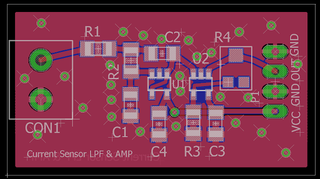
In this three part series we look at how to design a signal conditioning circuit to increase the accuracy and resolution of your ADC measurements. The signal conditioning circuit consists of a double pole active Sallen Key Low Pass Filter and a non-inverting op amp. The filter portion is meant to attenuate high frequency noise from your sensor signal to increase measurement accuracy. The amplifier portion scales the signal up to the full range of the ADC to ensure you are getting max resolution. In part 2 we do the PCB layout of our circuit using Eagle CAD software.


You can access the Eagle files on Github at: https://github.com/ForceTronics/Sallen-Key-Low-Pass-Filter-Design/tree/master


Tuesday, March 15, 2016

Building a Wireless Sensor Network with the nRF24L01 Part 5

In Part 5 of building a wireless sensor network with Arduino and the nRF24L01+ transceiver we take a look at our brand new PCB boards and look at the code for adding the DS18S20 and the STTS751 temperature sensors to the design. You can access the PCB Eagle files and the Arduino code from GitHub: https://github.com/ForceTronics/nRF24L01_Wireless_Sensor_Dev_Board


Tuesday, October 20, 2015

Building an Arduino Shield and Proto Board for the nRF24L01 Transceiver

The nRF24L01+ Transceiver is a great low cost way to add wireless capability to any project. But the down side of the nRF24L01+ is it can be a hassle to prototype with. In this video we look at how to build an Arduino shield and a mini proto board for the nRF24L01+. You can also purchase the shield and mini proto board covered in the video at forcetronics.com.


To Access the Eagle PCB files:
//*****************************Arduino Code for Transmitter***********************
//This sketch is from a tutorial video on the ForceTronics YouTube Channel. The tutorial discusses how to build a 
//shield and a prototyping board for the nRF24L01 Transceiver Module.
//the code was leverage from Ping pair example at http://tmrh20.github.io/RF24/pingpair_ack_8ino-example.html
//This sketch is free to the public to use and modify at your own risk

#include <SPI.h> //Call SPI library so you can communicate with the nRF24L01+
#include <nRF24L01.h> //nRF2401 libarary found at https://github.com/tmrh20/RF24/
#include <RF24.h> //nRF2401 libarary found at https://github.com/tmrh20/RF24/

const int pinCE = 9; //This pin is used to set the nRF24 to standby (0) or active mode (1)
const int pinCSN = 10; //This pin is used to tell the nRF24 whether the SPI communication is a command or message to send out
RF24 wirelessSPI(pinCE, pinCSN); // Create your nRF24 object or wireless SPI connection
const uint64_t pAddress = 0xB00B1E5000LL;   // Radio pipe addresses for the 2 nodes to communicate.

void setup()  
{
  Serial.begin(57600);   //start serial to communicate process
  wirelessSPI.begin();            //Start the nRF24 module
  wirelessSPI.setAutoAck(1);                    // Ensure autoACK is enabled so rec sends ack packet to let you know it got the transmit packet payload
  wirelessSPI.setRetries(5,15);                 // Sets up retries and timing for packets that were not ack'd, current settings: smallest time between retries, max no. of retries
  wirelessSPI.openWritingPipe(pAddress);        // pipe address that we will communicate over, must be the same for each nRF24 module
  wirelessSPI.stopListening();
}

void loop()  
{
   byte t = analogRead(0);//note that we can cast the ADC value to a byte because we know the temp sensor is not going to return a value higher than 255
   if (!wirelessSPI.write(&t, 1 )){  //if the send fails let the user know over serial monitor
       Serial.println("packet delivery failed");      
   }
    delay(1000);
}

//*****************************Arduino Code for Receiver***********************
//This sketch is from a tutorial video on the ForceTronics YouTube Channel. The tutorial discusses how to build a 
//shield and a prototyping board for the nRF24L01 Transceiver Module.
//the code was leverage from Ping pair example at http://tmrh20.github.io/RF24/pingpair_ack_8ino-example.html
//This sketch is free to the public to use and modify at your own risk

#include <SPI.h> //Call SPI library so you can communicate with the nRF24L01+
#include <nRF24L01.h> //nRF2401 libarary found at https://github.com/tmrh20/RF24/
#include <RF24.h> //nRF2401 libarary found at https://github.com/tmrh20/RF24/

const int pinCE = 9; //This pin is used to set the nRF24 to standby (0) or active mode (1)
const int pinCSN = 10; //This pin is used to tell the nRF24 whether the SPI communication is a command or message to send out
byte bVal; //used to store ADC value payload from transmit module, the ADC value will be < 256 so it will fit in a byte
RF24 wirelessSPI(pinCE, pinCSN); // Declare object from nRF24 library (Create your wireless SPI) 
const uint64_t pAddress = 0xB00B1E5000LL;  //Create a pipe addresses for the 2 nodes to communicate over, the "LL" is for LongLong type

void setup()   
{
  Serial.begin(57600);  //start serial to communicate process
  wirelessSPI.begin();  //Start the nRF24 module
  wirelessSPI.setAutoAck(1);                    // Ensure autoACK is enabled, this means rec send acknowledge packet to tell xmit that it got the packet with no problems
  wirelessSPI.openReadingPipe(1,pAddress);      //open pipe o for recieving meassages with pipe address
  wirelessSPI.startListening();                 // Start listening for messages
}

void loop()  
{   
   //loop until all of the payload data is recieved, for this example loop should only run once
    while(wirelessSPI.available()){ 
     wirelessSPI.read( &bVal, 1 ); //read one byte of data and store it in bVal variable
     Serial.print("Temperature at transmitter is "); 
     Serial.print(calculateTempF(calculateArduinoVolt(bVal))); //convert the ADC value to a voltage value and than to a temperature value in F
     Serial.println(" F");
    }
 
  delay(200);    
}

//this function calculates temp in F from TMP36 temp sensor
float calculateTempF(float v1) { 
 float temp = 0;
 //calculate temp in C, .75 volts is 25 C. 10mV per degree
 if (v1 < .75) { temp = 25 - ((.75-v1)/.01); } //if below 25 C
 else if (v1 == .75) {temp = 25; }
 else { temp = 25 + ((v1 -.75)/.01); } //if above 25
 //convert to F
 temp =((temp*9)/5) + 32;
 return temp;
}

//This function takes an Arduino analog pin reading and converts it to a voltage value
float calculateArduinoVolt(int val) {
 float volt = (float)val * (5.0 / 1023.0); //convert ADC value to voltage
 return volt;
}


Wednesday, September 2, 2015

Contracting and Consulting Services for Open Source Hardware Design

This video provides an overview of ForceTronics LLC's contracting and consulting services. Whether you are a maker, entrepreneur, or a startup Forcetronics Contracting and Consulting Services can help turn your idea into reality leveraging the power of open source hardware.


If you are interested contact me on twitter or email:
  • Twitter: @ForceTronics
  • Email: forcetronics@gmail.com
Put “Contracting Services” or “Consulting Services” in the subject line


Tuesday, August 11, 2015

Building Your Own AVR / Arduino Internet of Things (IoT) Development Board Part 5

Welcome to the final installment of building your own AVR / Arduino compatible internet of things (IoT) development board. In part 5 we open up our new PCBs and build them up. We then do some testing to make sure everything is working correctly. Spoiler alert, this video has a happy ending with a working Arduino compatible board with Bluetooth 4.0 built-in. Below you will find a link to the Eagle files and the Arduino code for the test sketch.


Link to download Eagle files including: library file, project files, and Gerber files:
https://dl.dropboxusercontent.com/u/26591541/AVR_IoT_Board_Eagle_Files_8_8_15.zip


*******************Arduino Test Sketch************************************
//This sketch is to test a DIY Arduino compatiable board with Bluetooth 4.0 on it
//the board is targeted IoT applications. Details can be found of the ForceTronics 
//YouTube channel. This code is open for anybody to use and modify

int wValue = 1; //variable to hold write value (high or low)

void setup() {
   Serial.begin(115200); //start serial
}

void loop() {
  delay(1000);
  setPinMode(OUTPUT, INPUT); //set D2 to D7 as outputs, and D8 to D13 to inputs
  setDigWrite(false, wValue); //set group of pins to write and write high or low
  Serial.print("D2 thru D7 writing "); 
  Serial.println(wValue);
  Serial.println("D8 thru D13 reading the following values....");
  printDigPins(true); //print what dig pins read
  delay(1000);
  setPinMode(INPUT, OUTPUT); //set D2 to D7 as intputs, and D8 to D13 to outputs
  setDigWrite(true, wValue); //set group of pins to write and write high or low
  Serial.print("D8 thru D13 writing "); 
  Serial.println(wValue);
  Serial.println("D2 thru D7 reading the following values....");
  printDigPins(false); //print what dig pins read
  
  delay(1000);
  adcReads(); //read each ADC pin and print result
  
  if(wValue) wValue = 0; //toggle digital write value
  else wValue = 1;
  delay(1000);
}

//function sets D2 thru D7 to input / output and D8 thru D13 to input / output
void setPinMode(int smallMode, int bigMode) {
  for(int i=0;i<6;i++) {
    pinMode((i+2), smallMode);
    pinMode((i+8), bigMode);
  }  
}

//Writes high or low to group of digital pins
void setDigWrite(bool big, int state) {
  if(big) {
    for(int i=0;i<6;i++) {
      digitalWrite((i+8), state);
    }
  }
  else {
    for(int i=0;i<6;i++) {
      digitalWrite((i+2), state);
    }
  }
}

//does digital read on group of digital pins and prints results
void printDigPins(bool big) {
  if(big) {
    for(int i=0;i<6;i++) {
      Serial.print("Value at pin D");
      Serial.print((i+8));
      Serial.print(" --> ");
      Serial.println(digitalRead((i+8)));
    }
  }
  else {
    for(int i=0;i<6;i++) {
      Serial.print("Value at pin D");
      Serial.print((i+2));
      Serial.print(" --> ");
      Serial.println(digitalRead((i+2)));
    }
  }
}


//Reads each ADC pin and prints result
void adcReads() {
  for(int i=0; i<6; i++) {
    Serial.print("ADC value at Pin A");
    Serial.print(i);
    Serial.print(" --> ");
    Serial.println(analogRead(i));
  }
}