Showing posts with label avr. Show all posts

Friday, December 16, 2016

Measuring Wind Speed with an Anemometer and Arduino

In this video we look at how to measure wind speed using an anemometer and Arduino. This approach will work on both ARM and AVR based Arduinos.


//*****************Arduino anemometer sketch******************************
const byte interruptPin = 3; //anemomter input to digital pin
volatile unsigned long sTime = 0; //stores start time for wind speed calculation
unsigned long dataTimer = 0; //used to track how often to communicate data
volatile float pulseTime = 0; //stores time between one anemomter relay closing and the next
volatile float culPulseTime = 0; //stores cumulative pulsetimes for averaging
volatile bool start = true; //tracks when a new anemometer measurement starts
volatile unsigned int avgWindCount = 0; //stores anemometer relay counts for doing average wind speed
float aSetting = 60.0; //wind speed setting to signal alarm

void setup() {
  pinMode(13, OUTPUT); //setup LED pin to signal high wind alarm condition
  pinMode(interruptPin, INPUT_PULLUP); //set interrupt pin to input pullup
  attachInterrupt(interruptPin, anemometerISR, RISING); //setup interrupt on anemometer input pin, interrupt will occur whenever falling edge is detected
  dataTimer = millis(); //reset loop timer
}

void loop() {
 
  unsigned long rTime = millis();
  if((rTime - sTime) > 2500) pulseTime = 0; //if the wind speed has dropped below 1MPH than set it to zero
     
  if((rTime - dataTimer) > 1800){ //See if it is time to transmit
   
    detachInterrupt(interruptPin); //shut off wind speed measurement interrupt until done communication
    float aWSpeed = getAvgWindSpeed(culPulseTime,avgWindCount); //calculate average wind speed
    if(aWSpeed >= aSetting) digitalWrite(13, HIGH);   // high speed wind detected so turn the LED on
    else digitalWrite(13, LOW);   //no alarm so ensure LED is off
    culPulseTime = 0; //reset cumulative pulse counter
    avgWindCount = 0; //reset average wind count

    float aFreq = 0; //set to zero initially
    if(pulseTime > 0.0) aFreq = getAnemometerFreq(pulseTime); //calculate frequency in Hz of anemometer, only if pulsetime is non-zero
    float wSpeedMPH = getWindMPH(aFreq); //calculate wind speed in MPH, note that the 2.5 comes from anemometer data sheet
   
    Serial.begin(57600); //start serial monitor to communicate wind data
    Serial.println();
    Serial.println("...................................");
    Serial.print("Anemometer speed in Hz ");
    Serial.println(aFreq);
    Serial.print("Current wind speed is ");
    Serial.println(wSpeedMPH);
    Serial.print("Current average wind speed is ");
    Serial.println(aWSpeed);
    Serial.end(); //serial uses interrupts so we want to turn it off before we turn the wind measurement interrupts back on
   
    start = true; //reset start variable in case we missed wind data while communicating current data out
    attachInterrupt(digitalPinToInterrupt(interruptPin), anemometerISR, RISING); //turn interrupt back on
    dataTimer = millis(); //reset loop timer
  }
}

//using time between anemometer pulses calculate frequency of anemometer
float getAnemometerFreq(float pTime) { return (1/pTime); }
//Use anemometer frequency to calculate wind speed in MPH, note 2.5 comes from anemometer data sheet
float getWindMPH(float freq) { return (freq*2.5); }
//uses wind MPH value to calculate KPH
float getWindKPH(float wMPH) { return (wMPH*1.61); }
//Calculates average wind speed over given time period
float getAvgWindSpeed(float cPulse,int per) {
  if(per) return getWindMPH(getAnemometerFreq((float)(cPulse/per)));
  else return 0; //average wind speed is zero and we can't divide by zero
  }

//This is the interrupt service routine (ISR) for the anemometer input pin
//it is called whenever a falling edge is detected
void anemometerISR() {
  unsigned long cTime = millis(); //get current time
  if(!start) { //This is not the first pulse and we are not at 0 MPH so calculate time between pulses
   // test = cTime - sTime;
    pulseTime = (float)(cTime - sTime)/1000;
    culPulseTime += pulseTime; //add up pulse time measurements for averaging
    avgWindCount++; //anemomter went around so record for calculating average wind speed
  }
  sTime = cTime; //store current time for next pulse time calculation
  start = false; //we have our starting point for a wind speed measurement
}

Monday, February 8, 2016

The Watchdog Timer on Arduino

In this video we take a look at the Watchdog Timer on Arduino and the three different ways to configure it. We show a simple example using the Watchdog Timer and you can find the code from the example below.


//**********************Arduino Code*******************************
#include <avr/wdt.h> //Watch dog timer functions
#include <EEPROM.h> //library for using EEPROM

// Pin 13 has an LED connected on most Arduino boards.
int led = 13;
volatile int wSetting = 1; //variable to store WDT setting, make it volatile since it will be used in ISR

void setup() {
  wdt_disable(); //Datasheet recommends disabling WDT right away in case of low probabibliy event
  pinMode(led, OUTPUT); //set up the LED pin to output
  pinMode(2,INPUT_PULLUP); //setup pin 2 for input since we will be using it with our button
  getSettings(); //start serial settings menu to choose WDT setting
  //setup the watchdog Timer based on the setting
  if(wSetting == 1) setWDT(0b01000000); //set for interrupt
  else if(wSetting == 2) setWDT(0b00001000); //set for reset
  else setWDT(0b01001000); //set for interrupt and then reset
}

void loop() {
  
  if(!digitalRead(2)) { //check if button to reset WDT was pressed
    digitalWrite(led, LOW);    // turn the LED off by making the voltage LOW
    wdt_reset(); //Reset the WDT 
  }
}

//This function gets the WDT setting from the user using Serial comm
void getSettings() {
  Serial.begin(57600);
  Serial.println("We just started up......");
  byte b; //variable to store interrupt / reset tracker
  if(EEPROM.get(10, b)) { //check if interrupt occurred before reset
    Serial.println("...and an interrupt occurred.....");
    b = 0; //reset variable
    EEPROM.put(10,b);
  }
  Serial.println("Select the WDT setting: 1 --> interrupt, 2 --> reset, 3 --> interrupt and reset");
  //wait for user to input setting selection
  while (!Serial.available()) { }
  wSetting = Serial.parseInt(); //get entry and ensure it is valid
  if(wSetting < 1 || wSetting > 3) {
      wSetting = 1;
   }
   Serial.print("WDT setting is ");
   Serial.println(wSetting);
   Serial.println();
   Serial.end(); //don't want to mix serial comm and interrupts together
}

/*
void setSleepInterval(byte timer) {
  sleep_enable(); //enable the sleep mode
  set_sleep_mode(SLEEP_MODE_PWR_DOWN); //set the type of sleep mode. Default is Idle. power down saves the most power
  ADCSRA &= ~(1<<ADEN); //Turn off ADC before going to sleep (set ADEN bit to 0). this saves even more power
  WDTCSR |= 0b00011000;    //Set the WDE bit and then clear it when set the prescaler, WDCE bit must be set if changing WDE bit   
  WDTCSR = 0b01000000 | timer; //This sets the WDT to the interval specified in the function argument
  wdt_reset(); //Reset the WDT 
  sleep_cpu(); //enter sleep mode. Next code that will be executed is the ISR when interrupt wakes Arduino from sleep
  sleep_disable(); //disable sleep mode
  ADCSRA |= (1<<ADEN); //Turn the ADC back on
}*/

//this function setups up and starts the watchdog timer
void setWDT(byte sWDT) {
   WDTCSR |= 0b00011000;
   WDTCSR = sWDT |  WDTO_2S; //Set WDT based user setting and for 2 second interval
   wdt_reset();
}


//This is the interrupt service routine for the WDT. It is called when the WDT times out and is in interrupt mode. 
//This ISR must be in your Arduino sketch or else the WDT will not work correctly
ISR (WDT_vect) 
{
  digitalWrite(led, HIGH); 
  if(wSetting == 3) {
    byte b = 1;
    EEPROM.put(10, b);
  }
  //wdt_disable();
}  // end of WDT_vect

Monday, November 23, 2015

Getting Started with the Atmel Xplained Mini with the ATmega168PB MCU

In this video we give you an overview of the Atmel Xplained Mini which is a development board for the ATmega168PB microcontroller. In the video we cover how to load a simple "Blink" program onto the Xplained Mini with Atmel Studio and how the development board is compatible with Arduino Shields. The video is presented from the standpoint of an Arduino user. You can access the code from the video below.


//**************************Atmel Studio Code****************************
/*
 * ATmega168PB Example.c
 *
 * Created: 11/21/2015 4:59:24 PM
 * Author : ForceTronics
 */ 

#define F_CPU 16000000UL //Set the clock frequency
#include <avr/io.h> //call IO library
#include <util/delay.h> //call delay library

int main(void)
{
DDRB |= (1<<DDB5); //Set Port B 5 or PB5 or PCINT5 or pin 17 to output (1 is output and 0 is input)
while(1)
{
/*
PORTB |= (1<<PORTB5);    //Set PB5 to 1 which is high (LED on)
_delay_ms(1000);        //Delay for 1000ms or 1 sec
PORTB &= ~(1<<PORTB5);    //Set PB5 to 0 which is low (LED off)
_delay_ms(1000);        //Delay for 1000ms or 1 sec
*/
PINB |= (1<<PINB5);
_delay_ms(1000);        //Delay for 1000ms or 1 sec
}
}


Friday, October 30, 2015

Building a Arduino Uno Compatible Circuit

Ever want to remove the microcontroller off the Arduino board to better integrate it into your project or design. In this video we do just that with Atmel ATmega 328P MCU found on the Arduino Uno. We will look at the bare bones circuit setup needed to run the 328P as well as how to still program it with the Arduino IDE. All the parts shown in this video can be purchased from forcetronics.com.


Tuesday, August 11, 2015

Building Your Own AVR / Arduino Internet of Things (IoT) Development Board Part 5

Welcome to the final installment of building your own AVR / Arduino compatible internet of things (IoT) development board. In part 5 we open up our new PCBs and build them up. We then do some testing to make sure everything is working correctly. Spoiler alert, this video has a happy ending with a working Arduino compatible board with Bluetooth 4.0 built-in. Below you will find a link to the Eagle files and the Arduino code for the test sketch.


Link to download Eagle files including: library file, project files, and Gerber files:
https://dl.dropboxusercontent.com/u/26591541/AVR_IoT_Board_Eagle_Files_8_8_15.zip


*******************Arduino Test Sketch************************************
//This sketch is to test a DIY Arduino compatiable board with Bluetooth 4.0 on it
//the board is targeted IoT applications. Details can be found of the ForceTronics 
//YouTube channel. This code is open for anybody to use and modify

int wValue = 1; //variable to hold write value (high or low)

void setup() {
   Serial.begin(115200); //start serial
}

void loop() {
  delay(1000);
  setPinMode(OUTPUT, INPUT); //set D2 to D7 as outputs, and D8 to D13 to inputs
  setDigWrite(false, wValue); //set group of pins to write and write high or low
  Serial.print("D2 thru D7 writing "); 
  Serial.println(wValue);
  Serial.println("D8 thru D13 reading the following values....");
  printDigPins(true); //print what dig pins read
  delay(1000);
  setPinMode(INPUT, OUTPUT); //set D2 to D7 as intputs, and D8 to D13 to outputs
  setDigWrite(true, wValue); //set group of pins to write and write high or low
  Serial.print("D8 thru D13 writing "); 
  Serial.println(wValue);
  Serial.println("D2 thru D7 reading the following values....");
  printDigPins(false); //print what dig pins read
  
  delay(1000);
  adcReads(); //read each ADC pin and print result
  
  if(wValue) wValue = 0; //toggle digital write value
  else wValue = 1;
  delay(1000);
}

//function sets D2 thru D7 to input / output and D8 thru D13 to input / output
void setPinMode(int smallMode, int bigMode) {
  for(int i=0;i<6;i++) {
    pinMode((i+2), smallMode);
    pinMode((i+8), bigMode);
  }  
}

//Writes high or low to group of digital pins
void setDigWrite(bool big, int state) {
  if(big) {
    for(int i=0;i<6;i++) {
      digitalWrite((i+8), state);
    }
  }
  else {
    for(int i=0;i<6;i++) {
      digitalWrite((i+2), state);
    }
  }
}

//does digital read on group of digital pins and prints results
void printDigPins(bool big) {
  if(big) {
    for(int i=0;i<6;i++) {
      Serial.print("Value at pin D");
      Serial.print((i+8));
      Serial.print(" --> ");
      Serial.println(digitalRead((i+8)));
    }
  }
  else {
    for(int i=0;i<6;i++) {
      Serial.print("Value at pin D");
      Serial.print((i+2));
      Serial.print(" --> ");
      Serial.println(digitalRead((i+2)));
    }
  }
}


//Reads each ADC pin and prints result
void adcReads() {
  for(int i=0; i<6; i++) {
    Serial.print("ADC value at Pin A");
    Serial.print(i);
    Serial.print(" --> ");
    Serial.println(analogRead(i));
  }
}

Friday, July 10, 2015

Building Your Own AVR / Arduino Internet of Things (IoT) Development Board Part 4

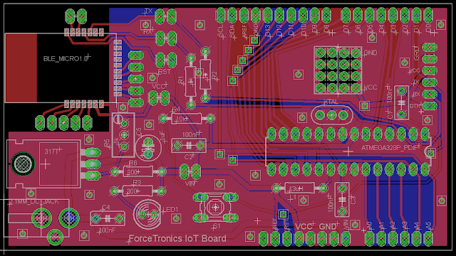
This is part 4 in a 5 part series where we build our own AVR / Arduino Internet of Things (IoT) development board, yay! In this part we will do the PCB layout and discuss how to get our PCB manufactured.


Download Eagle Files


Eagle Parts and Libraries
Libraries Used:
•Atmega 328P --> Library: SparkFun-DigitalIC Device: ATMEGA328P_PDIP
•LM317 --> Library: linear>*317 Device:317T
•Resonator ZTT16.0MHz --> Library: Adafruit Device: CERMOSCILL-THM (CERMOSCILL)
•Ceramic Cap --> Library: rcl > C-EU Device: C-EU050-030X075
•Electrolytic cap --> Library: rcl > CPOL-EU Device: CPOL-EUE2.5-6
•Resistor --> Library: resistor Device: R-EU_0207/10 (R-EU_) Package: 0207/10
•Reset switch --> Library: switch-omron Device: 10-XX
•LED --> Library: led Device: LED5MM (LED)
•Potentiometer --> Library: rcl > R-TRIMM Device: R-TRIMMT93YA
Note: Sparkfun and Adafruit libraries did not come with Eagle, but you can find them on their websites

Parts I made (included in files linked to my blog):
•ForceTronic.lbr --> All header and pin holes and 2.1mm DC Jack
•BLE_Micro_Module.lbr --> BLE Micro

Monday, July 6, 2015

Building Your Own AVR / Arduino Internet of Things (IoT) Development Board Part 3

This is part 3 in a 5 part series where we build our own AVR / Arduino Internet of Things (IoT) development board, yay! In this part we will finalize our design schematic and parts list so we are ready to do PCB layout in part 4.


Final Design Schematic:


Bill of Materials:
  • Atmega 328P MCU (Dip Package)
  • 16MHz resonator
  • BLE Micro from DFRobot or equivalent
  • LM317 Voltage Regulator
  • Resistors (Ohms): 10k, 2x 1k, 2x 300, 1k POTENTIOMETER or 500
  • Capacitors: 4x 100nF (Ceramic) and 1uF (electrolytic)
  • LED 5mm (any color you want)
  • 0.1” male pins
  • 2x 0.1” 2x4 female header (optional)
  • 4x 0.1” pin jumpers
  • DC Power Jack (+ pin is 2.1mm) 
  • 13uH Inductor (optional)
  • Female pin headers: 6 pin, 2x 8 pin, 10 pin
  • 28 pin DIP Socket (optional): part # 4828-3004-CP

Wednesday, June 17, 2015

Building Your Own AVR / Arduino Internet of Things (IoT) Development Board Part 2

This is part 2 in a 5 part series where we build our own AVR / Arduino Internet of Things (IoT) development board, yay! In this part we add the Arduino bootloader to our Atmega 328p as well as build and test a prototype of our design.


BLE Micro Shield Eagle Files 1.0 version (use at your own risk):
https://dl.dropboxusercontent.com/u/26591541/BLE%20Shield.zip


//*******************Arduino Code**********************************************
/*
  This sketch is part of a video tutorial on the ForceTronics YouTube Channel for Building Your AVR/Arduino IoT Development Board 
  which uses a Atmega 328p and a Bluetooth low energy module. 
  The bluetooth module is connected to an Arduino and the Arduino is connected to an LED. 

  This code is in the public domain.
 */

// Pin 13 has a LED connected to it
int led = 13;

// the setup routine runs once when you press reset:
void setup() {
  
  Serial.begin(115200);
  // initialize the digital pin as an output and set it low initially
  pinMode(led, OUTPUT);
  digitalWrite(led, LOW);
}

// the loop routine runs over and over again forever:
void loop() {
  delay(30);
  String t; //create an empty string to store messages from Android
  while(Serial.available()) { //keep reading bytes while they are still more in the buffer
    t += (char)Serial.read(); //read byte, convert to char, and append it to string
  }
  
  if(t.length()) { //if string is not empty do the following
    if(t == "on") { //if the string is equal to "on" then turn LED on
      digitalWrite(led, HIGH); //Set digital pin to high to turn LED on
      Serial.write("LED is on"); //Tell the Android app that the LED was turned on
    }
    else if (t == "off") { 
      digitalWrite(led, LOW);  
      Serial.write("LED is off");
    } // turn the LED off by making the voltage LOW
  }
}

Tuesday, June 2, 2015

Building Your Own AVR / Arduino Internet of Things (IoT) Development Board Part 1

In this 5 part video series we will build our own AVR / Arduino Internet of Things (IoT) development board. We will go from a design concept to prototyping our design to PCB layout of our design all the way to a tested and finished development board.


Example parts order for this project (please note that this does not include all the parts)


Sunday, April 19, 2015

Reducing Arduino’s Power Consumption Part 4 (Turning Off the BOD)

This is the fourth, and most likely the last, in a series where we look at how to reduce your Arduino's power consumption. This series is great for anybody working on a project that is battery powered and you want to ensure the longest battery life possible. In this part we will look at how to turn off the Brown Out Detector (BOD) to save power.


************************Arduino Code*******************************************
/* This Arduino Sketch is part of a tutorial on the ForceTronics YouTube Channel and demonstrates how to use the Sleep cabilities on
Arduino as well as turn off the ADC to get low power consumption. In this tutorial the Extended Fuse on the Atmega was configured
to turn off the Brown Out Detection (BOD) for even further power savings. It is free and open for anybody to use at their own risk.
*/

/*
To turn off the BOD avrdude was used via the command prompt, the following command was used:
avrdude -c usbtiny -p atmega328p -U efuse:w:0x07:m
*/

#include <avr/sleep.h>

void setup() {
  delay(6000); //Delay to see normal power level first
  sleep_enable(); //enable the sleep capability
  set_sleep_mode(SLEEP_MODE_PWR_DOWN); //set the type of sleep mode. Default is Idle
  ADCSRA &= ~(1<<ADEN); //Turn off ADC before going to sleep (set ADEN bit to 0)
  sleep_cpu(); //enter sleep mode. Next code that will be executed is the ISR when interrupt wakes Arduino from sleep
}

void loop() {
  // put your main code here, to run repeatedly:
}

Thursday, December 11, 2014

Reducing Arduino’s Power Consumption Part 3

Welcome to part 3 of reducing Arduino's power consumption, a must watch series for anybody building a battery powered project with Arduino. In part 3 we will look at how to use the Watch Dog Timer like an alarm clock to wake Arduino up from sleep mode. We we also look at some additional techniques to save power.


*****************************************Arduino Code*************************************************
/*
Example program for using sleep modes and watch dog timer in Arduino. This example code was used in a sleep mode tutorial video on the ForceTronics YouTube Channel.
This code is open for anybody to use at their own risk*/
     
/*WDT BYTE variables for setting timer value
     WDTO_15MS
WDTO_30MS
WDTO_60MS
WDTO_120MS
WDTO_250MS
WDTO_500MS
WDTO_1S
WDTO_2S
WDTO_4S
WDTO_8S */
     
#include <avr/sleep.h>
//We use part of the WDT library, but have to use registers as well since library does not support interrupt mode for WDT
#include <avr/wdt.h> 

int led = 13; //variable for pin that the LED is on
int tog = 1; //variable that toggles between traditional delay() function and WDT sleep delay function

void setup() {
  wdt_disable(); //Datasheet recommends disabling WDT right away in case of low probabibliy event
   pinMode(led, OUTPUT); //set up the LED pin to output
}

void loop() {
  
  if(tog) { //use traditional delay function
    digitalWrite(led, HIGH);   // turn the LED on (HIGH is the voltage level)
    delay(1000);               // wait 
    digitalWrite(led, LOW);    // turn the LED off by making the voltage LOW
    delay(1000);       // wait 
    tog = 0; //toggle variable
  }
  else { //after blinking LED setup interrupt and then go to sleep. Note that sleep will only happen once sinc
    digitalWrite(led, HIGH);   // turn the LED on (HIGH is the voltage level)
    delay(1000);   // turn the LED on (HIGH is the voltage level)//  
    digitalWrite(led, LOW);    // turn the LED off by making the voltage LOW
    delayWDT(WDTO_1S);   // Use WDT sleep delay function, argument is byte variable from WDT Library
    //delayWDT(0x06);      //Use WDT sleep delay function, argument is byte value that sets timer to 1 second
    tog = 1; //toggle variable
  }
   
}

//This function serves as a power saving delay function. The argument is a Byte type variable that is used to set the delay time
//The function sets up sleep mode in power down state. The function then sets up the WDT timer in interrupt mode and sets it.
//It then puts the Arduino to sleep for the set time. Upon wake up the WDT and sleep mode are shut off
void delayWDT(byte timer) {
  sleep_enable(); //enable the sleep capability
  set_sleep_mode(SLEEP_MODE_PWR_DOWN); //set the type of sleep mode. Default is Idle
  ADCSRA &= ~(1<<ADEN); //Turn off ADC before going to sleep (set ADEN bit to 0)
  WDTCSR |= 0b00011000;    //Set the WDE bit and then clear it when set the prescaler, WDCE bit must be set if changing WDE bit   
  WDTCSR =  0b01000000 | timer; //Or timer prescaler byte value with interrupt selectrion bit set
 // WDTCSR = 0b01000110; //This sets the WDT to 1 second
  wdt_reset(); //Reset the WDT 
  sleep_cpu(); //enter sleep mode. Next code that will be executed is the ISR when interrupt wakes Arduino from sleep
  sleep_disable(); //disable sleep mode
  ADCSRA |= (1<<ADEN); //Turn the ADC back on
}

//This is the interrupt service routine for the WDT. It is called when the WDT times out. 
//This ISR must be in your Arduino sketch or else the WDT will not work correctly
ISR (WDT_vect) 
{
  wdt_disable();
   MCUSR = 0; //Clear WDT flag since it is disabled, this is optional

}  // end of WDT_vect

Sunday, November 30, 2014

Reducing Arduino’s Power Consumption Part 2

In Part two, of this three part series, we will look at how to use the Power Reduction Register (PRR) to reduce power consumption by turning off parts of Arduino that are not being used. This series is for anybody using Arduino for a battery powered project where maximizing battery life is critical.


*************************Arduino Code***********************************
/* This Arduino Sketch is part of a tutorial on the ForceTronics YouTube Channel and demonstrates how to use the 
Power Reduction Registers (PRR). It is free and open for anybody to use at their own risk.
*/

#include <avr/power.h>
     
 /* Power Reduction Register (PRR) functions from avr/power.h library. 
 For every disable function there is an enable function
  power_adc_disable() or power_adc_enable()
  power_spi_disable() or power_spi_enable()
  power_timer0_disable() or power_timer0_enable()
  power_timer1_disable() or power_timer1_enable()
  power_timer2_disable() or power_timer2_enable()
  power_twi_disable() or power_twi_enable()
  power_all_enable() or power_all_disable()
  
  Note that for max power efficiency you should also disable the rest of the module for ADC and SPI
   SPCR = 0; //disable SPI
   ADCSRA = 0;  // disable ADC
  */

void setup() {
  delay(6000); //Delay to see normal power level first
  ADCSRA = 0;  // disable ADC by setting ADCSRA register to 0
  power_adc_disable(); //disable the clock to the ADC module
  delay(4000); //delay to see just ADC off power level
  SPCR = 0; //disable SPI by setting SPCR register to 0
  power_spi_disable(); //disable the clock to the SPI module
  delay(4000); //delay to see just ADC and SPI off power level
  power_all_disable();
}

void loop() {
  // put your main code here, to run repeatedly:
}