The ForceTronics blog provides tutorials on creating fun and unique electronic projects. The goal of each project will be to create a foundation or jumping off point for amateur, hobbyist, and professional engineers to build on and innovate. Please use the comments section for questions and go to forcetronics.com for information on forcetronics consulting services.
In this two part series we take a look at mechanical relays: different types, terminology, theory of operation, and design considerations. We finish part one with a demo of an armature relay showing its inside, how to actuate it, and capture its flyback voltage waveform with an Oscilloscope. In part 2 we look at a simple circuit that allows us to control armature or reed relays with a simple digital pin from a microcontroller. We also look at a circuit design that allows us to avoid hot switching when using mechanical relays.
Check us out on Patreon for exclusive content related to this series: https://www.patreon.com/forcetronics
In this video series we implement an adjustable LED Drive circuit using the AL8862FF-7. In part 1 we review the target LED applications for our drive circuit and how the switch mode buck architecture of the AL8862FF-7 LED drive IC works. We then look at the schematic design for our circuit. In part 2 we look at a demo of our LED Drive Circuit in action. We also take a look at the PCB layout of the LED Drive Circuit. At the end we look at measurement data from our circuit including the max and adjusted current values as well as look at measurements to calculate the efficiency of the design. The extended Patreon version of the video include more measurement data on the design and reviews the ESP32 Arduino code used in the demo.
Link to ForceTronics Patreon Page: https://www.patreon.com/forcetronics
AL8862FF-7 datasheet: https://www.mouser.com/datasheet/2/115/AL8862-1274720.pdf
This video series will take you step by step through how to design a circuit that can be powered from a USB input (5V) or from a Lithium Ion battery cell and output a regulated 5V. The design includes a battery charging circuit and a circuit that automatically isolates the battery from the power bus when USB power is applied.
In part one we review the overall plan for the design, go over Li-ion battery cell basics, and give a crash course on boost switching voltage regulators.
Battery university link: https://batteryuniversity.com/
In part two we go into detail on our boost switching regulator design using Texas Instruments TPS61202 5-V fixed output voltage boost converter.
Link to TI’s TPS61202 product page: https://www.ti.com/product/TPS61202?qgpn=tps61202
In part three we look at the battery charging circuit and the power source isolation circuit
Link to MAX1898 battery charging IC datasheet: https://www.mouser.com/datasheet/2/256/MAX1898-1515496.pdf
In part 4 we look at the PCB layout for our circuits and we see a demo of our circuits in action
In this video we give an overview of the USB type-C connector standard along with other related USB standards. We then look at an example design that implements a USB type-C connector and converts the USB 2.0 communication to serial or UART communication. You can then use the serial data to communicate, debug, or program your microcontroller for programming environments such as Arduino.
In this two part series we look at how to control a Solenoid using an ESP32 board and the Arduino IoT Cloud. In part one we focus on what a solenoid is and the hardware needed to drive a solenoid open or closed. In part 2 we focus on setting up the Arduino IoT Cloud control.
In this tutorial we look at how to combat switch bounce when using a rotary encoder with a debounce circuit made up of fairly basic components (see below). We use the KY-040 encoder as the test subject in the video. Below is the parts list from the video.
Parts list: BAS16-HE3-18 (Diode), SN74LVC1G17QDCKRQ1 (Schmitt Trigger), standard 0805 resistors (300ohms and 15kohms), and 4.7uF 0805 ceramic capacitor
Code from example ESP32 and KY-040 application in the video
//This sketch demonstrates how to use the KY-040 encoder
//link to KY-040 https://www.epitran.it/ebayDrive/datasheet/25.pdf
//encoder pins
#include <Adafruit_NeoPixel.h>
#define ECLK 26 //encoder CLK pin
#define EDT 25 //encoder DT pin
#define ESW 35 //encoder SW pin
#define LED_PIN 13 //pin for LED comm
#define LED_CNT 1 //LED cnt
#define BRIGHTNESS 125 //LED brightness setting
//First argument is number of LEDs, second is arduino pin
Adafruit_NeoPixel pixels = Adafruit_NeoPixel(LED_CNT,LED_PIN, NEO_GRB + NEO_KHZ800);
const uint32_t off = pixels.Color(0, 0, 0); //RGB value for off
const uint32_t white = pixels.Color(127, 127, 127); //RGB color for white
const uint32_t blue = pixels.Color(30,144,255); //RGB color for blue
const uint32_t red = pixels.Color(255, 0, 0); //RGB color for red
volatile bool buttonFlag = false; //flag that tracks if button was pressed
volatile uint8_t encoderFlag = 0; //flog for tracking encoder turns
bool ledState = false; //tracks whether to turn LED off or on for button presses
//interrupt service routine for an encoder turn CC or CCW
void IRAM_ATTR ISR() { encoderFlag = true; }
//interrupt service routine for an encoder button press
void IRAM_ATTR ISR2() {
buttonFlag = true;
}
void setup() {
pinMode(ECLK,INPUT); //setup encoder pins
pinMode(EDT,INPUT);
pinMode(ESW,INPUT);
attachInterrupt(ECLK, ISR, FALLING); //setup encoder interrupts
attachInterrupt(ESW, ISR2, FALLING);
pixels.begin(); //start RGB LED object
pixels.setBrightness(BRIGHTNESS); //set LED brightness
setLED(off); //set LED off
}
void loop() {
if(encoderFlag) { //encoder knob was turned
if(digitalRead(EDT)) { //encoder turned clockwise
setLED(blue);
}
else { //encoder was turned counter clockwise
setLED(red);
}
encoderFlag = false; //reset flag
}
if(buttonFlag) { //button was pressed
buttonFlag = false; //reset flag
if(ledState) {
setLED(off);
ledState = false;
}
else {
setLED(white);
ledState = true;
}
}
}
//sets LED to a specified RGB color
//input is the RGB value
void setLED(uint32_t color) {
for(int i=0;i<1;i++){
pixels.setPixelColor(i,color); //set LED color
pixels.show(); //send updated state to LED
}
}
In this video we look at how to setup and change the system clock on the SAMD21 family of microcontrollers from Microchip / Atmel. This example code is written in C++ and uses direct register access.
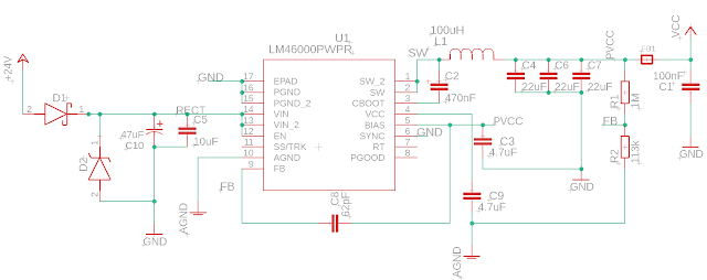
In the video we look at how to design a 24VAC power supply for industrial and HVAC applications. The supply will be flexible enough to handle DC voltage inputs. The power supply will employ a DC to DC buck converter, half wave rectifier, input protection against over voltage, and output noise reduction circuit features. In part 2 we look at the PCB design, the finished product, and capture some test data to see how it is working.
In the video we look at how to design a 24VAC power supply for industrial and HVAC applications. The supply will be flexible enough to handle DC voltage inputs. The power supply will employ a DC to DC buck converter, half wave rectifier, input protection against over voltage, and output noise reduction circuit features
Link to the ferrite bead article mentioned in the video: https://www.analog.com/en/analog-dialogue/articles/ferrite-beads-demystified.html#
Link to TI Webbench Power Designer tool: https://webench.ti.com/power-designer/switching-regulator
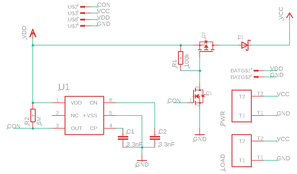
In this video we will design an automatic battery cutoff circuit to prevent damaging over discharge of rechargeable batteries. In part 2 we test the design and discuss MOSFET and Voltage Detector specs.
BOM of battery cutoff circuit:
S-1011A70-M6T1U4 Voltage Detector from ABLIC
DMP4015SSS-13 P Chan MOSFET from Diodes Inc
BSS138 N Chan MOSFET from multiple manufacturers
RSX051VYM30FHTR Schottky Diode from ROHM Semi
2x 3.3 nF Ceramic Capacitor
~100 kOhm Resistor
1 to 10 MOhm Resistor (used 4.7M in example circuit)
In this video we will design an automatic battery cutoff circuit to prevent damaging over discharge of rechargeable batteries. To design our battery cutoff circuit we will use a Voltage Detector or Reset IC.
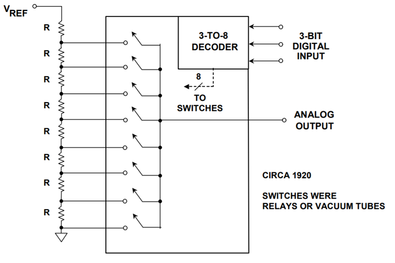
In part two of this 4 or 5 part series, we look at how the Successive Approximation or SAR ADC architecture works and understand its limitations. Note SAR based ADC architecture is what you typically find in microcontrollers.
Two part tutorial on digital to analog converters (DAC). In part 2 we take a look at the capabilities of the MCP4728 which is a four channel DAC controlled via I2C. See the links below to access the code and get the PCB design from the video at PCBWay.
Link for PCB board at PCBWay: https://www.pcbway.com/project/shareproject/W08904ASW106_DAC_Example_Gerber.html
//**********Arduino Code with MCP4728 examples from video*************** /* * This code was written to demonstrate functions on the MCP4728 4 channel DAC for a video on the ForceTronics YouTube channel * This sketch leverages a library from GitHub made by Hideakitai, link to library: https://github.com/hideakitai/MCP4728 * This code is public domain and free to anyone to use and modify with no restrictions at your own risk */ #include <Wire.h> #include "MCP4728.h" MCP4728 dac; //create object to library //variables for wavform int const sampleCount = 24; //samples to read to have a buffer int signalSamples[sampleCount]; //create array to hold signal or waveform float pi2 = 6.283; //value of pi times 2 const long clkFrequency = 400000; //I2C clock frequency const uint8_t t1 = 3; //pin to setup test 1 fast sinewave const uint8_t t2 = 4; //pin to setup test 2 sync'd sinewaves const uint8_t LDAC = 5; //Output pin on MCU to control LDAC(not) pin on DAC void setup() { //Create sinewave float in; float hBit = 2047.5; for (int i=0;i<sampleCount;i++) { in = pi2*(1/(float)sampleCount)*(float)i; signalSamples[i] = (int)(sin(in)*hBit + hBit); } pinMode(t1,INPUT_PULLUP); //configure test check pins pinMode(t2,INPUT_PULLUP); //configure test check pins pinMode(LDAC,OUTPUT); //configure test check pins digitalWrite(LDAC,HIGH); //turn DAC outputs off Wire.begin(); //start up I2C library Wire.setClock(clkFrequency); //set clock frequency for I2C comm dac.attatch(Wire, 13); //second argument is Arduino pin connected to LDAC(not), we are controlling LDAC manually so just entered pin we are not using dac.readRegisters(); //Used to read current settings from MCP4728 dac.selectVref(MCP4728::VREF::VDD, MCP4728::VREF::VDD, MCP4728::VREF::VDD, MCP4728::VREF::VDD); //setup voltage ref for each DAC channel dac.selectPowerDown(MCP4728::PWR_DOWN::NORMAL, MCP4728::PWR_DOWN::NORMAL, MCP4728::PWR_DOWN::NORMAL, MCP4728::PWR_DOWN::NORMAL); //set power down mode, used for saving power dac.selectGain(MCP4728::GAIN::X1, MCP4728::GAIN::X1, MCP4728::GAIN::X1, MCP4728::GAIN::X1); //set gain on output amp //dac.enable(true); //enables the DAC outputs by controlling LDAC pin, but we are controlling LDAC manually in this example //perform test one if(!digitalRead(t1)) { digitalWrite(LDAC,LOW); //output sinewave as fast as we can for(;;) { //run test for infinitity for(int j=0;j<sampleCount;j++) { dac.analogWrite(MCP4728::DAC_CH::A,signalSamples[j]); } } } else { //perform test 2 for(;;) { //run test for infinitity for(int j=0;j<sampleCount;j++) { int temp = j; digitalWrite(LDAC,HIGH); //turn outputs off // delay(1); dac.analogWrite(MCP4728::DAC_CH::A,signalSamples[temp]); temp += 8; //shift sigal 90 degrees if(temp > 23) temp -= sampleCount; dac.analogWrite(MCP4728::DAC_CH::B,signalSamples[temp]); temp += 8; //shift sigal 90 degrees if(temp > 23) temp -= sampleCount; dac.analogWrite(MCP4728::DAC_CH::C,signalSamples[temp]); temp += 8; //shift sigal 90 degrees if(temp > 23) temp -= sampleCount; dac.analogWrite(MCP4728::DAC_CH::D,signalSamples[temp]); digitalWrite(LDAC,LOW); //turn outputs on all four outputs at same time // delay(1); } } } } void loop() { }
In this video we go over what a digital to analog converter (DAC) is and how it works. We then focus on the MCP4728 4 Channel DAC with some simple examples. In part two we do a deeper dive into the MCP4728.
In this series we look at how to design a Thermocouple temperature measurement circuit. In part 2 we look at a real world example of a Thermocouple J Type circuit design and discuss some of the common sources of error and how to avoid them.
In this series we look at how to design a Thermocouple temperature measurement circuit. In part 1 we look at Thermocouple theory, pros and cons versus other temperature measurement techniques, and an overview of a measurement hardware circuit as well as calculations done in software.
In this video we look at an easy way with not very much code to setup a wireless network using the nRF24L01 Transceiver and Arduino.
//***************************Master or Receiver code***************** /*This code was used for a video tutorial on the ForceTronics YouTube Channel * This code is free and open for anybody to use and modify at your own risk */ #include <SPI.h> //Call SPI library so you can communicate with the nRF24L01+ #include <nRF24L01.h> //nRF2401 libarary found at https://github.com/tmrh20/RF24/ #include <RF24.h> //nRF2401 libarary found at https://github.com/tmrh20/RF24/ const uint8_t pinCE = 9; //This pin is used to set the nRF24 to standby (0) or active mode (1) const uint8_t pinCSN = 10; //This pin is used for SPI comm chip select RF24 wirelessSPI(pinCE, pinCSN); // Declare object from nRF24 library (Create your wireless SPI) const uint64_t rAddress = 0xB00B1E50C3LL; //Create pipe address for the network and notice I spelled boobies because I am mature, the "LL" is for LongLong type const uint8_t rFChan = 89; //Set channel frequency default (chan 84 is 2.484GHz to 2.489GHz) //Create a structure to hold fake sensor data and channel data struct PayLoad { uint8_t chan; uint8_t sensor; }; PayLoad payload; //create struct object void setup() { wirelessSPI.begin(); //Start the nRF24 module wirelessSPI.setChannel(rFChan); //set communication frequency channel wirelessSPI.openReadingPipe(1,rAddress); //This is receiver or master so we need to be ready to read data from transmitters wirelessSPI.startListening(); // Start listening for messages Serial.begin(115200); //serial port to display received data Serial.println("Network master is online..."); } void loop() { if(wirelessSPI.available()){ //Check if recieved data wirelessSPI.read(&payload, sizeof(payload)); //read packet of data and store it in struct object Serial.print("Received data packet from node: "); Serial.println(payload.chan); //print node number or channel Serial.print("Node sensor value is: "); Serial.println(payload.sensor); //print node's sensor value Serial.println(); } }
//***************************Node or Transmitter code***************** /*This code was used for a video tutorial on the ForceTronics YouTube Channel * This code is free and open for anybody to use and modify at your own risk */ #include <SPI.h> //Call SPI library so you can communicate with the nRF24L01+ #include <nRF24L01.h> //nRF2401 libarary found at https://github.com/tmrh20/RF24/ #include <RF24.h> //nRF2401 libarary found at https://github.com/tmrh20/RF24/ const uint8_t pinCE = 9; //This pin is used to set the nRF24 to standby (0) or active mode (1) const uint8_t pinCSN = 10; //This pin is used to tell the nRF24 whether the SPI communication is a command RF24 wirelessSPI(pinCE, pinCSN); // Declare object from nRF24 library (Create your wireless SPI) const uint64_t wAddress = 0xB00B1E50C3LL; //Create pipe address to send data, the "LL" is for LongLong type const uint8_t rFChan = 89; //Set channel default (chan 84 is 2.484GHz to 2.489GHz) const uint8_t rDelay = 7; //this is based on 250us increments, 0 is 250us so 7 is 2 ms const uint8_t rNum = 5; //number of retries that will be attempted const uint8_t chan1 = 2; //D2 pin for node channel check const uint8_t chan2 = 3; //D3 pin for node channel check const uint8_t chan3 = 4; //D4 pin for node channel check //stuct of payload to send fake sensor data and node channel struct PayLoad { uint8_t chan; uint8_t sensor; }; PayLoad payload; //create struct object void setup() { pinMode(chan1,INPUT_PULLUP); //set channel select digital pins to input pullup pinMode(chan2,INPUT_PULLUP); pinMode(chan3,INPUT_PULLUP); wirelessSPI.begin(); //Start the nRF24 module wirelessSPI.setChannel(rFChan); wirelessSPI.setRetries(rDelay,rNum); //if a transmit fails to reach receiver (no ack packet) then this sets retry attempts and delay between retries wirelessSPI.openWritingPipe(wAddress); //open writing or transmit pipe wirelessSPI.stopListening(); //go into transmit mode randomSeed(analogRead(0)); //set random seed for fake sensor data setChannel(); //checks current channel setting for transceiver } void loop() { delay(3000); //send data every 3 seconds payload.sensor = random(0,255); //get made up sensor value if (!wirelessSPI.write(&payload, sizeof(payload))){ //send data and remember it will retry if it fails delay(random(5,20)); //as another back up, delay for a random amount of time and try again if (!wirelessSPI.write(&payload, sizeof(payload))){ //set error flag if it fails again } } } //check for low digital pin to set node address void setChannel() { if(!digitalRead(chan1)) payload.chan = 1; else if(!digitalRead(chan2)) payload.chan = 2; else if(!digitalRead(chan3)) payload.chan = 3; else payload.chan = 0; }
In this video look at how to create a bridge that takes data from the UART port and writes it to a file on a USB thumb drive (BOMS device). For this project we will use the FT900 microcontroller from FTDI / Bridgetek.
/* Code from the video*********************************************************** * This is code was used for a Tutorial on the ForceTronics YouTube Channel on writing UART data to a file on a USB thumb drive * Most of this code was leveraged from the FTDI / Bridgetek example program called "USBH Example File System" it was written for the FT900 * family of microcontrollers from FTDI / Bridgetek. This code is free and open for any to use or modify at their own risk * */ //all these includes come from the example "USBH Example File System" made by FTDI #include <stdint.h> #include <string.h> #include <ft900.h> #include <ft900_usb.h> #include <ft900_usbh_boms.h> #include <ft900_startup_dfu.h> // UART support for printf output #include "tinyprintf.h" // Support for FATFS #include "ff.h" #include "diskio.h" /* CONSTANTS ***********************************************************************/ #define EXAMPLE_FILE "FTronics.TXT" // Change this value in order to change the size of the buffer being used #define RINGBUFFER_SIZE (4096) /* GLOBAL VARIABLES ****************************************************************/ // File system handle for fatfs. FATFS fs; // Context structure and handle for BOMS device. USBH_BOMS_context bomsCtx; USBH_interface_handle hOpenDisk = 0; USBH_device_handle hRootDev; unsigned long fPosition = 0; //This variable is used to track the position in the file where the last data was written volatile unsigned int mTimer = 0; //This variable was used to test how long it took to write data to the file typedef struct //struct for buffer that stores UART data before it is written to file { uint8_t data[RINGBUFFER_SIZE]; uint16_t wr_idx; uint16_t rd_idx; } RingBuffer_t; // Receiver buffer static RingBuffer_t uart0BufferIn = { {0}, 0, 0 }; /* LOCAL FUNCTIONS / INLINES *******************************************************/ DSTATUS disk_initialize(BYTE pdrv); DSTATUS disk_status(BYTE pdrv); DRESULT disk_read (BYTE pdrv, BYTE* buff, DWORD sector, UINT count); DRESULT disk_write (BYTE pdrv, const BYTE* buff, DWORD sector, UINT count); DRESULT disk_ioctl (BYTE pdrv, BYTE cmd, void* buff); DWORD get_fattime(void); /** @name tfp_putc * @details Machine dependent putc function for tfp_printf (tinyprintf) library. * @param p Parameters (machine dependent) * @param c The character to write */ void tfp_putc(void* p, char c) { uart_write((ft900_uart_regs_t*)p, (uint8_t)c); } void ISR_timer(void) //this interrupt fires every ten milliseconds to handle USB functions { if (timer_is_interrupted(timer_select_a)) { // Call USB timer handler to action transaction and hub timers. USBH_timer(); mTimer++; } } /* FatFS Functions ******************/ /** Initialise a drive * @param pdrv Physical Drive number * @return Disk Status */ DSTATUS disk_initialize(BYTE pdrv) { DSTATUS stat = 0; int8_t status; status = USBH_BOMS_init(hOpenDisk, 0, &bomsCtx); if (status != USBH_BOMS_OK) { tfp_printf("BOMS device could not be initialised: %d\r\n", status); stat = STA_NOINIT; hOpenDisk = 0; } return stat; } /** Disk Status * @param pdrv Physical Drive number * @return Disk Status */ DSTATUS disk_status(BYTE pdrv) { DSTATUS stat = 0; if (0 == hOpenDisk) { stat |= STA_NOINIT; } //TODO: perform a GetSense SCSI command to make sure it's there if (USBH_BOMS_status(&bomsCtx) != USBH_BOMS_OK) { stat |= STA_NODISK; } return stat; } /** Read sector(s) from disk * @param pdrv Physical Drive number * @param buff Data buffer to store into * @param sector The logical sector address * @param count The number of sectors to read * @return Disk Status */ DRESULT disk_read (BYTE pdrv, BYTE* buff, DWORD sector, UINT count) { DRESULT res = RES_OK; if (USBH_BOMS_read(&bomsCtx, sector, USBH_BOMS_BLOCK_SIZE * count, buff) != USBH_BOMS_OK) { res = RES_ERROR; } return res; } #if _USE_WRITE /** Write sector(s) to the disk * @param pdrv Physical Drive number * @param buff Data buffer to write to the disk * @param sector The logical sector address * @param count The number of sectors to write * @return Disk Status */ DRESULT disk_write (BYTE pdrv, const BYTE* buff, DWORD sector, UINT count) { DRESULT res = RES_OK; if (USBH_BOMS_write(&bomsCtx, sector, USBH_BOMS_BLOCK_SIZE * count, (uint8_t *)buff) != USBH_BOMS_OK) { res = RES_ERROR; } return res; } #endif #if _USE_IOCTL /** Disk IO Control * @param pdrv Physical Drive Number * @param cmd Control Code * @param buff Buffer to send/receive control data * @return Disk Status */ DRESULT disk_ioctl (BYTE pdrv, BYTE cmd, void* buff) { DRESULT res = RES_OK; /* Not Supported */ return res; } #endif #if _FS_READONLY == 0 /** Get the current time * @return The time in the following format: * bit[31:25] = Year from 1980 (0..127), * bit[24:21] = Month (1..12), * bit[20:16] = Day of the Month (1..31), * bit[15:11] = Hour (0..23), * bit[10:5] = Minute (0..59), * bit[4..0] = Second / 2 (0..29) */ DWORD get_fattime(void) { return 0; /* Invalid timestamp */ } #endif /** See how much data is available in the UART0 ring buffer @return The number of bytes available */ uint16_t uart0Available(void) { int16_t diff = uart0BufferIn.wr_idx - uart0BufferIn.rd_idx; if (diff < 0) { diff += RINGBUFFER_SIZE; } return (uint16_t)diff; } /** Receive a number of bytes from UART0 @return The number of bytes read from UART0 */ uint16_t uart0Rx(uint8_t *data, uint16_t len) { uint16_t avail = 0; uint16_t copied = 0; avail = uart0Available(); /* Copy in as much data as we can ... This can be either the maximum size of the buffer being given or the maximum number of bytes available in the Serial Port buffer */ while(len-- && avail--) { *data = uart0BufferIn.data[uart0BufferIn.rd_idx]; data++; /* Increment the pointer and wrap around */ uart0BufferIn.rd_idx++; if (uart0BufferIn.rd_idx == RINGBUFFER_SIZE) uart0BufferIn.rd_idx = 0; copied++; } /* Report back how many bytes have been copied into the buffer...*/ return copied; } /** The Interrupt which handles asynchronous transmission and reception of data into the ring buffer */ void uart0ISR() { static uint8_t c; /* Receive interrupt... */ if (uart_is_interrupted(UART0, uart_interrupt_rx)) { /* Read a byte into the Ring Buffer... */ uart_read(UART0, &c); uart0BufferIn.data[uart0BufferIn.wr_idx] = c; /* Increment the pointer and wrap around */ uart0BufferIn.wr_idx++; if (uart0BufferIn.wr_idx == RINGBUFFER_SIZE) uart0BufferIn.wr_idx = 0; /* Check to see if we have hit the back of the buffer... */ if (uart0BufferIn.wr_idx == uart0BufferIn.rd_idx) { /* Increment the pointer and wrap around */ uart0BufferIn.rd_idx++; if (uart0BufferIn.rd_idx == RINGBUFFER_SIZE) uart0BufferIn.rd_idx = 0; } } } //this function mounts file system that the file is written to int8_t mountFileSystem(USBH_interface_handle hBOMS) { // Initialise FatFS hOpenDisk = hBOMS; //this gets USB "interface" handle //Would like to make this a one time action if (f_mount(&fs, "", 0) != FR_OK) //mounts file system, needed to open file I am assuming { tfp_printf("Unable to mount File System\r\n"); return -1; } tfp_printf("\r\n\r\n"); delayms(1000); return 0; } //This function creates the file that we are storing on the USB drive //If the file already exists it will be deleted and a new one is created int8_t createFile(USBH_interface_handle hBOMS) { // Initialise FatFS hOpenDisk = hBOMS; //this gets USB "interface" handle FRESULT res; //file data type, that is an enumeration with states of the file interactions FIL f; //another file data type enum with file conditions // Check to see if the example file is there. //This code checks to see if file already exists res = f_stat(EXAMPLE_FILE, NULL); if (FR_OK == res) { tfp_printf("File " EXAMPLE_FILE " already exists. Deleting\r\n"); if (FR_OK != f_unlink(EXAMPLE_FILE)) { tfp_printf("Problem deleting " EXAMPLE_FILE "\r\n"); return 0; } } res = f_open(&f, EXAMPLE_FILE, FA_CREATE_NEW); if (FR_OK != res) { tfp_printf("Problem creating file " EXAMPLE_FILE "\r\n"); return 0; } tfp_printf( "Closing " EXAMPLE_FILE "\r\n"); if (FR_OK != f_close(&f)) //This is where the file is closed after writing { tfp_printf("Error closing " EXAMPLE_FILE "\r\n"); } tfp_printf("\r\n\r\n"); delayms(1000); return 1; } //funciton used to write data to the file. the data pointer is for the data you want to write //this bCount variable is for how much data int8_t writeDataToFile(USBH_interface_handle hBOMS, uint8_t* data, uint16_t bCount) { FRESULT res; //file data type, that is an enumeration with states of the file interactions FIL f; //another file data type enum with file conditions UINT towrite, written; // Initialise FatFS hOpenDisk = hBOMS; //this gets USB "interface" handle which I am guessing is information on the USB device we are working with // Write some data to the USB memory stick, this is where we open file to write to // tfp_printf( "Opening " EXAMPLE_FILE " for writing\r\n"); res = f_open(&f, EXAMPLE_FILE, FA_WRITE | FA_OPEN_EXISTING); if (FR_OK != res) { tfp_printf("Problem opening file " EXAMPLE_FILE "\r\n"); } f_lseek (&f, fPosition); //change writing position of the file??? towrite = bCount; written = 0; //this is where we write the data to the file. It seems if you mess up setting up USB stuff this is where we fail while(towrite) { f_write(&f, data, towrite, &written); towrite -= written; data += written; tfp_printf("Wrote %d bytes\r\n", written); } fPosition = fPosition + written; tfp_printf( "Closing " EXAMPLE_FILE "\r\n"); if (FR_OK != f_close(&f)) //This is where the file is closed after writing { tfp_printf("Error closing " EXAMPLE_FILE "\r\n"); } return 0; } //This funciton will read data from file. It is not used in this example and was left in for debugging purposes int8_t readFromFile(USBH_interface_handle hBOMS) { FIL f; //another file data type enum with file conditions UINT read; uint8_t* buffer[512]; //buffer for reading file on USB BOMS // Initialise FatFS hOpenDisk = hBOMS; //this gets USB "interface" handle which I am guessing is information on the USB device we are working with //this is where the / a file is open and read tfp_printf( "Opening " EXAMPLE_FILE " for reading\r\n\r\n"); if (FR_OK != f_open(&f, EXAMPLE_FILE, FA_READ)) { tfp_printf("Error opening " EXAMPLE_FILE " for reading\r\n"); } do { f_read(&f, buffer, 128, &read); uart_writen(UART0, (uint8_t *)buffer, read); } while(read == 128); tfp_printf( "\r\n" "Closing " EXAMPLE_FILE "\r\n"); f_close(&f); tfp_printf("\r\n\r\n"); return 0; } //this function does all the setup work for the connected USB drive USBH_interface_handle doAllUSBStuff(){ uint8_t status; USBH_STATE connect; USBH_interface_handle hInterface; uint8_t usbClass; uint8_t usbSubclass; uint8_t usbProtocol; //First USB action, initialize. There is no function for this so is it part of the USBH library //This is part of FT900 USB library, notes from doc:Performs a software reset and initialises the USB hardware USBH_initialise(NULL); //Second step: Determine if a hub port has a downstream connection. //Select a hub and a port to query. For the root hub the handle will be NULL and the port zero //checks if there are multiple ports, and sets if there is a connection USBH_get_connect_state(USBH_ROOT_HUB_HANDLE, USBH_ROOT_HUB_PORT, &connect); if (connect == USBH_STATE_NOTCONNECTED) { tfp_printf("\r\nPlease plug in a USB Device\r\n"); // You only enter this loop if there is no USB device detected. basically loops until you plug one in do //looks like this is only called if the first port call fails { //Third step: To be continuously called by the user application. Checks for asynchronous transfer completions //and root hub events. When a root hub connection is detected then the enumeration routine is called automatically. //There is no requirement to call USBH_enumerate if USBH_process is called periodically. status = USBH_process(); USBH_get_connect_state(USBH_ROOT_HUB_HANDLE, USBH_ROOT_HUB_PORT, &connect); } while (connect == USBH_STATE_NOTCONNECTED); } tfp_printf("\r\nUSB Device Detected\r\n"); do{ //this loop continues until USB BOMS device is enumerated status = USBH_process(); //third step, see description above //USBH_process combined with get connected state does the enumeration USBH_get_connect_state(USBH_ROOT_HUB_HANDLE, USBH_ROOT_HUB_PORT, &connect); } while (connect != USBH_STATE_ENUMERATED); tfp_printf("USB Device Enumerated\r\n"); // Get the first device (device on root hub) //Step four: Get device list. Get the first child device of a device. The function will return a handle to a device if there are one //or more child devices. For devices on the root hub the handle is set to USBH_ROOT_HUB_HANDLE.If there are no interfaces then a NULL is returned. status = USBH_get_device_list(USBH_ROOT_HUB_HANDLE, &hRootDev); if (status != USBH_OK) { // Report the error code. tfp_printf("%d\r\n", status); } else //this is where hub_scan_for_boms function was orginally called in USB test function { //this is a repeated function call (step 4), why do that? probably just to get status data in this function rather than //passing it from previous function status = USBH_get_interface_list(hRootDev, &hInterface); //step 5: Get interface class, subclass and protocol. Get the class information of an interface. //This function basically gets the USB characteristics of the attached device if (USBH_interface_get_class_info(hInterface, &usbClass, &usbSubclass, &usbProtocol) == USBH_OK) { if ((usbClass == USB_CLASS_MASS_STORAGE) && //this if statement is checking all the parameters of the previous function (usbSubclass == USB_SUBCLASS_MASS_STORAGE_SCSI) && (usbProtocol == USB_PROTOCOL_MASS_STORAGE_BOMS)) { tfp_printf("BOMS device found at level %d\r\n", 1); //at this point we have established the connected USB device and we are moving to the file interactions //fs_testing(hInterface,"this better print to a mofo text file"); mountFileSystem(hInterface); } else { tfp_printf("Problem creating and writing to file"); } } else { tfp_printf("Problem getting USB information"); } } return hInterface; } void setup() { /* Check for a USB device connection and initiate a DFU firmware download or upload operation. This will timeout and return control here if no host PC program contacts the device's DFU interace. USB device mode is disabled before returning. */ STARTUP_DFU(); /* Enable the UART Device... */ sys_enable(sys_device_uart0); /* Make GPIO48 function as UART0_TXD and GPIO49 function as UART0_RXD... */ gpio_function(48, pad_uart0_txd); /* UART0 TXD */ gpio_function(49, pad_uart0_rxd); /* UART0 RXD */ uart_open(UART0, /* Device */ 1, /* Prescaler = 1 */ UART_DIVIDER_115200_BAUD, /* Divider = 1302 */ uart_data_bits_8, /* No. Data Bits */ uart_parity_none, /* Parity */ uart_stop_bits_1); /* No. Stop Bits */ // Enable tfp_printf() functionality... init_printf(UART0, tfp_putc); sys_enable(sys_device_timer_wdt); interrupt_attach(interrupt_timers, (int8_t)interrupt_timers, ISR_timer); // Timer A = 1ms timer_prescaler(1000); timer_init(timer_select_a, 1000, timer_direction_down, timer_prescaler_select_on, timer_mode_continuous); timer_enable_interrupt(timer_select_a); timer_start(timer_select_a); uart_disable_interrupt(UART0, uart_interrupt_tx); // Enable the UART to fire interrupts when receiving data... uart_enable_interrupt(UART0, uart_interrupt_rx); // Attach the interrupt so it can be called... interrupt_attach(interrupt_uart0, (uint8_t) interrupt_uart0, uart0ISR); // Enable interrupts to be fired... uart_enable_interrupts_globally(UART0); interrupt_enable_globally(); hOpenDisk = doAllUSBStuff(); createFile(hOpenDisk); } int main(int argc, char *argv[]) { setup(); //run code to setup USB and UART communication fPosition = 0; //reset the file position while(1) { //loop forever mTimer = 0; //reset 10 msec timer variable if (uart0Available()) { uint8_t buffer[RINGBUFFER_SIZE] = {0}; uint16_t read_bytes = uart0Rx(buffer, RINGBUFFER_SIZE); writeDataToFile(hOpenDisk, buffer, read_bytes); tfp_printf("timer value is %d\r\n", mTimer*10); } } interrupt_detach(interrupt_timers); interrupt_disable_globally(); sys_disable(sys_device_timer_wdt); }