Welcome back for part 4 of building a wireless temperature sensor network. In part 3 we looked at some design options for powering our wireless sensors, DC power supply and battery technologies, as well as options for implementing a voltage conversion stage, DC to DC converter and voltage regulator. For our wireless temperature sensor network we will be powering the network controller with a low cost 9 V DC power supply. Voltage conversion from 9 V to 5 V for the controller will be handled by the Arduino Uno's built-in voltage regulator. For sensor 1 we will be using a 7.4 V Li-ion Polymer battery pack as our power source and a voltage regulator to convert the battery voltage to a 3.3 V level. For sensor 2 we will be using 4 series AA Alkaline batteries as our power source and a DC to DC converter to convert the battery voltage to a 3.3 V level.
Since batteries have a finite amount of power we need a way in our sensor 1 and 2 design to monitor the battery voltage level so we know when it is time to replace or recharge them. Besides just knowing when they need to be replaced, there is another important reason why we need to monitor the battery voltage level and that is to ensure we do not over discharge them. Over discharging batteries is a bad thing especially when it comes to Li-ion battery technologies (if you did your battery homework from part 3 you would already know this). For the Li-ion Polymer battery pack we do not want to let the voltage level to go below 6 V. One way to ensure that this does not happen is to measure the battery level periodically and notify the user when the battery level starts to approach 6 V. We could use one of the XBee's ADC pins to measure the battery level, but the ADC can only read voltage levels up to 1.2 V. So how can we measure > 6 V with an ADC that can only read up to 1.2 V? The answer is we implement a voltage divider between the battery output and ground. Our voltage divider will consist of two resistors of known values in series. The resistor closet to the battery output will be higher in value than the resistor closet to ground. We then connect the ADC pin between the two resistors. This yields a lower voltage level (a divided down voltage level) at the ADC pin, but since we know the values of the resistors we can use this lower measured voltage level to calculate the voltage level at the battery's output. Let's take a look at an updated schematic diagram of sensor 1 and 2 with our new power system added, including our voltage divider for monitoring the battery voltage level.
 |
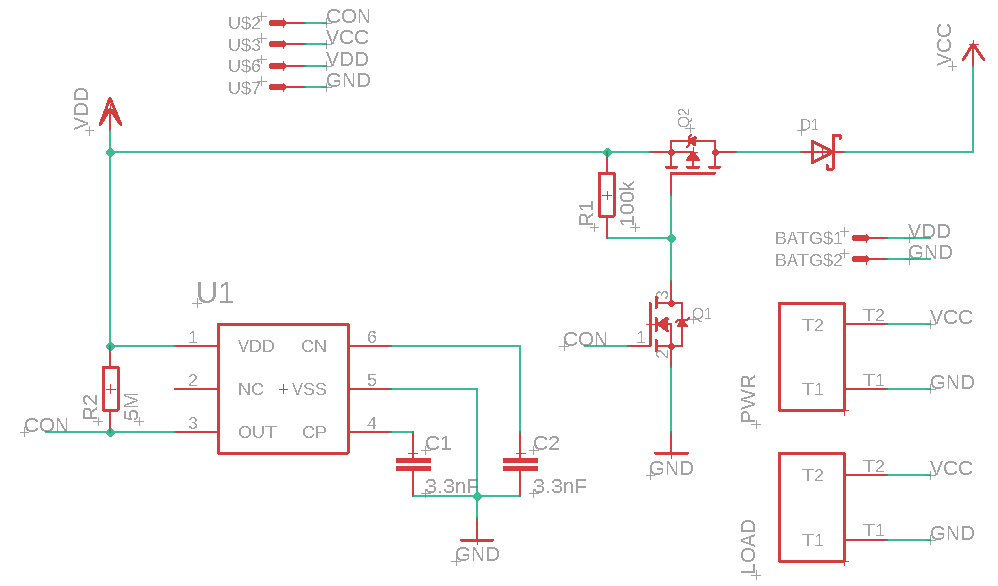
| Sensor 1 and 2 with power design |
The voltage divider for sensor 1 and 2 is made up of the 150 kOhm and 15 kOhm resistors. For simplicity sake we will use the same divider design and low voltage level (6.0 V) for both the Li-ion Polymer battery pack and Alkaline batteries. Notice that connected in-between our voltage divider is the AD2 pin of the XBee, this is the ADC pin we will use to monitor the battery voltage level. The voltage divider resistors were chosen so that the resistor closet to the battery is 10 times larger than the resistor closet to ground (150 k / 15 k = 10). That means the voltage level at the ADC pin of the XBee will be 1/10 the value of the battery voltage. As an example, if the ADC measures 0.68 V we know the battery voltage level is 6.8 V (0.68 x 10 = 6.8). Since 6.8 V is larger than 6.0 V we know that our battery is still good.
The downside of our voltage divider circuit is that it wastes battery power since there is current flowing through it to ground. That is why we want to use high value resistors like 150 kOhm to keep the current flowing through the voltage divider to a minimum. You may be asking yourself, why not use even higher value resistors like 10 MOhm and 1 MOhm? The reason is that the XBee ADC pin has a finite resistance value. When making an ADC measurement, the ADC pin presents a 1 MOhm resistance to the circuit it is connected to (this information was obtained from the XBee manual). That means when AD2 makes a measurement it is like putting a 1 MOhm resistor in parallel with the resistor closet to ground in the voltage divider circuit. If the resistor closet to ground had a resistance value close to 1 MOhm, the ADC measurement itself would essentially change the circuit and the resulting measurement would not be accurate. So for the voltage divider we want it to be high enough in resistance so that we do not waste too much battery life, but low enough so that the ADC input resistance does not have a drastic effect on measurement accuracy. With a total series resistance of 165 kOhm in our voltage divider it only consumes ~ 42 uA of current (7 V / 165 kOhm).
With the new power design and the need to monitor the battery voltage level we have to update our XBee router firmware and the Arduino Uno code. For the XBee routers the only change we want to make to the firmware is to set pin AD2 from disabled (0) to ADC (2), everything else for the routers will stay the same. With this change in the firmware the XBee routers will now make two ADC readings every 5 seconds (one on pin AD2 and one on pin AD3). Below is the updated code for the Arduino Uno.
/*This sketch was written for the Arduino Uno. The Uno has an XBee Series 2 RF Module connected to it as a coordinator. The Uno uses the XBee coordinator to communicate with two XBee routers. Each XBee router has an analog pin set to measure a temperature sensor and a second analog pin set to measure the voltage level of the battery power the XBee. This program receives the temperature readings from the two router XBees and writes the data to the serial monitor. It also monitors the battery voltage level, if the battery level falls below 6.2 V it signals the user via the serial monitor that the battery is low. This sketch is part of a tutorial on building a wireless sensor network, the tutorial can be found at http://forcetronic.blogspot.com/*/
/*Each Xbee has a unque 64 bit address. The first 32 bits are common to all XBee. The following four ints (each int holds an address byte) hold the unique 32 bits of the XBee address*/
int addr1;
int addr2;
int addr3;
int addr4;
int sen3Counter = 0; //This counter variable is used print sensor 3 every 5 seconds
float batDead = 6.2; //battery pack voltage level where it needs to be replaced
void setup() {
Serial.begin(9600); //start the serial communication
}
void loop() {
if (Serial.available() >= 23) { // Wait for a full XBee frame to be ready
if (Serial.read() == 0x7E) { // Look for 7E because it is the start byte
for (int i = 1; i<19; i++) { // Skip through the frame to get to the unique 32 bit address
//get each byte of the XBee address
if(i == 8) { addr1 = Serial.read(); }
else if (i==9) { addr2 = Serial.read(); }
else if (i==10) { addr3 = Serial.read(); }
else if (i==11) { addr4 = Serial.read(); }
else { byte discardByte = Serial.read(); } //else throwout byte we don't need it
}
int aMSBBat = Serial.read(); // Read the first analog byte of battery voltage level data
int aLSBBat = Serial.read(); // Read the second byte
int aMSBTemp = Serial.read(); // Read the first analog byte of temperature data
int aLSBTemp = Serial.read(); // Read the second byte
float voltTemp = calculateXBeeVolt(aMSBTemp, aLSBTemp); //Get XBee analog values and convert to voltage values
float voltBat = calculateBatVolt(aMSBBat, aLSBBat); //Get Xbee analog value and convert it to battery voltage level
if(voltBat > batDead) { //This if else checks the battery voltage, if it is too low alert the user
Serial.println(indentifySensor(addr1,addr2,addr3,addr4)); //get identity of XBee and print the indentity
Serial.print("Temperature in F: ");
Serial.println(calculateTempF(voltTemp)); //calculate temperature value from voltage value
}
else {
Serial.println(indentifySensor(addr1,addr2,addr3,addr4)); //get identity of XBee and print the indentity
Serial.print("Low battery voltage: ");
Serial.println(voltBat); //print battery pack voltage level
}
}
}
delay(10); //delay to allow operations to complete
//This if else statement is used to print the reading from sensor 3 once every 5 second to match the //XBee routers it uses the delay() function above to calculate 5 seconds
if (sen3Counter < 500) { sen3Counter++; }
else {
Serial.println("Temperature from sensor 3:");//This is sensor 3
Serial.print("Temperature in F: ");
Serial.println(calculateTempF(calculateArduinoVolt(analogRead(A0))));
sen3Counter = 0; //reset counter back to zero
}
}
//This function takes XBee address and returns the identity of the Xbee that sent the temperature data
String indentifySensor(int a1, int a2, int a3, int a4) {
//These arrays are the unique 32 bit address of the two XBees in the network
int rout1[] = {0x40, 0xB0, 0xA3, 0xA6};
int rout2[] = {0x40, 0xB0, 0x87, 0x85};
if(a1==rout1[0] && a2==rout1[1] && a3==rout1[2] && a4==rout1[3]) {
return "Temperature from sensor 1:"; //temp data is from XBee one
}
else if(a1==rout2[0] && a2==rout2[1] && a3==rout2[2] && a4==rout2[3]) {
return "Temperature from sensor 2:"; } //temp data is from XBee two
else { return "I don't know this sensor"; } //Data is from an unknown XBee
}
float calculateTempF(float v1) { //calculate temp in F from temp sensor
float temp = 0; //calculate temp in C, .75 volts is 25 C. 10mV per degree
if (v1 < .75) { temp = 25 - ((.75-v1)/.01); } //if below 25 C
else if (v1 == .75) {temp = 25; }
else { temp = 25 + ((v1 -.75)/.01); } //if above 25
//convert to F
temp =((temp*9)/5) + 32;
return temp;
}
//This function takes an XBee analog pin reading and converts it to a voltage value
float calculateXBeeVolt(int analogMSB, int analogLSB) {
int analogReading = analogLSB + (analogMSB * 256); //Turn the two bytes into an integer value
float volt = (float)analogReading*(1.2/1023); //Convert the analog value to a voltage value
return volt;
}
//This function takes an Arduino analog pin reading and converts it to a voltage value
float calculateArduinoVolt(int val) {
float volt = (float)val * (5.0 / 1023.0); //convert ADC value to voltage
return volt;
}
//This function calculates the measured voltage of the battery powering the sensor
float calculateBatVolt(int aMSB, int aLSB) {
float mult = 10.0; //multiplier for calculating battery voltage
return (calculateXBeeVolt(aMSB, aLSB)*mult); //xbee volt x volt divider multiplier equals battery voltage
}
Notice from the code that the beginning of the data frame is the same the only difference is instead of just reading two bytes of analog data, we are now reading four (two readings). In the calculateBatVolt() function a multiplier of '10' is used to calculate the battery voltage, this multiplier is based on the ratio of the resisters used in the voltage divider circuit. A value of 6.2 V was used to represent a low battery level. This value was used to give a buffer zone between when you get the low battery voltage warning and when you were actually able to get to the battery and remove it from the circuit. Remember that even though you are getting a notification of a low battery, the battery is still being drained until you actually disconnect it from the circuit. As mentioned before over discharging a rechargeable battery can damage it. Below is a screen capture of a serial monitor showing our new power designs and code in action.

With sensor 1 and 2 being battery powered I spread them out over my house. Sensor 3, the controller, was placed near a drafty window hence the low reading. Notice that the sensor 2 battery voltage level drops below 6.2 V and signals the user of a low battery condition.
Well that is it for part 4, you now are equipped to add a power source, voltage conversion stage, and power source monitoring circuit to your temperature sensor designs. In part 5 we will add two new capabilities to our wireless temperature sensor network: internet monitoring and logging readings to non-volatile memory. To do this we will replace the Arduino Uno that we have been using in our controller with an Arduino Yun. If you have any questions on what was covered here feel free to asked them in the comments section below or email me at forcetronics@gmail.com.