Showing posts with label battery. Show all posts

Friday, January 6, 2023

Designing a Li-Ion and USB Power Circuit with Built-in Charging

This video series will take you step by step through how to design a circuit that can be powered from a USB input (5V) or from a Lithium Ion battery cell and output a regulated 5V. The design includes a battery charging circuit and a circuit that automatically isolates the battery from the power bus when USB power is applied.

Please support ForceTronics on Patreon: patreon.com/forcetronics

In part one we review the overall plan for the design, go over Li-ion battery cell basics, and give a crash course on boost switching voltage regulators.


Battery university link: https://batteryuniversity.com/


In part two we go into detail on our boost switching regulator design using Texas Instruments TPS61202 5-V fixed output voltage boost converter.


Link to TI’s TPS61202 product page: https://www.ti.com/product/TPS61202?qgpn=tps61202

In part three we look at the battery charging circuit and the power source isolation circuit


Link to MAX1898 battery charging IC datasheet: https://www.mouser.com/datasheet/2/256/MAX1898-1515496.pdf

In part 4 we look at the PCB layout for our circuits and we see a demo of our circuits in action


Circuit Block Diagram


Monday, December 9, 2019

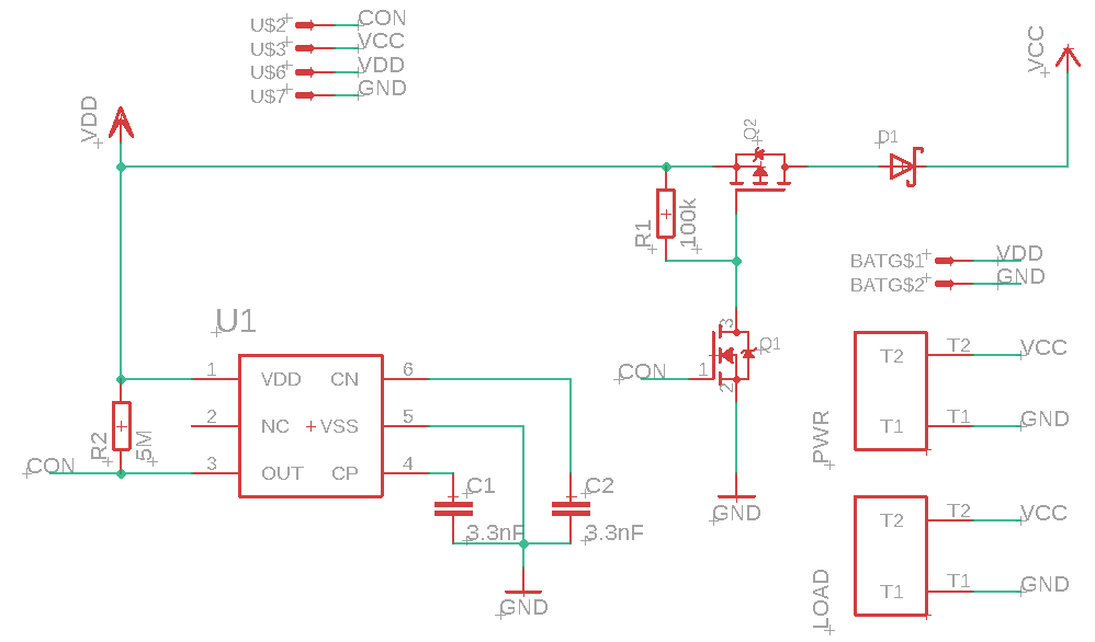
Designing an Automatic Battery Cutoff Circuit to Prevent Over Discharge of Rechargeable Batteries Part 2

In this video we will design an automatic battery cutoff circuit to prevent damaging over discharge of rechargeable batteries. In part 2 we test the design and discuss MOSFET and Voltage Detector specs.


BOM of battery cutoff circuit: 
  • S-1011A70-M6T1U4 Voltage Detector from ABLIC
  • DMP4015SSS-13 P Chan MOSFET from Diodes Inc
  • BSS138 N Chan MOSFET from multiple manufacturers
  • RSX051VYM30FHTR Schottky Diode from ROHM Semi
  • 2x 3.3 nF Ceramic Capacitor
  • ~100 kOhm Resistor
  • 1 to 10 MOhm Resistor (used 4.7M in example circuit)

PCB Layout of Battery Cutoff Circuit

Friday, November 29, 2019

Designing an Automatic Battery Cutoff Circuit to Prevent Over Discharge of Rechargeable Batteries Part 1

In this video we will design an automatic battery cutoff circuit to prevent damaging over discharge of rechargeable batteries. To design our battery cutoff circuit we will use a Voltage Detector or Reset IC.


BOM from video:

  • S-1011A70-M6T1U4 Voltage Detector from ABLIC 
  • DMP4015SSS-13 P Chan MOSFET from Diodes Inc 
  • BSS138 N Chan MOSFET from multiple manufacturers 
  • RSX051VYM30FHTR Schottky Diode from ROHM Semi 
  • 2x 3.3 nF Ceramic Capacitor 
  • ~100 kOhm Resistor 
  • 1 to 10 MOhm Resistor

Battery Cutoff Circuit Schematic

Tuesday, December 12, 2017

Ultimate Battery Circuit Design Part 2

In this video series we build the ultimate battery circuit that can handle various battery chemistry's, charge batteries, perform load sharing during charging, handle input voltage levels that are higher or lower than the output, and more. In part 2 we will look at the PCB layout with a focus on the buck boost DC to DC Converter and look at the BOM.


Sunday, December 3, 2017

Ultimate Battery Circuit Design Part 1

In this video series we build the ultimate battery circuit that can handle various battery chemistry's, charge batteries, perform load sharing during charging, handle input voltage levels that are higher or lower than the output, and more. In part 1 we will look at the circuit configuration and component values that we plan to use.


Sunday, November 5, 2017

How to Build a Simple DC Electronic Load with Arduino Part 2

In this video we look at how to make a simple DC electronic load with Arduino and some simple components. In part two 2 we add some flexible measurement capabilities.


//***************************Arduino Code*************************************************
#include <Average.h> /* * This code was used for a tutorial on how to build a simple eload with Arduino * The Tutorial can be found on the ForceTronics YouTube Channel * This code is public domain and free for anybody to use at their own risk */ //Uncomment AVGMEAS to print out avg measurement data and uncomment FASTMEAS to print fast voltage or current measur #define AVGMEAS //#define FASTMEAS //uncomment to print fast current measurements, leave commented to print fast voltage measurements //#define FASTAMP //The following variables set the eload sequence const int sValues[] = {20,50,280}; //set the DAC value for each step const unsigned long sTime[] = {350,50,15}; //set the dwell time for each step const int sNum = 3; //number of steps in the sequence, this number should match the number or items in the arrays long repeat = -1; //set the number of times the sequence repeats, -1 means infinite //The following variables control the measurement rates int measInterval = 5; //in milli seconds, fast measurement rate. This should be less than or equal to measAvgInt int measAvgInt = 1000; //this is done in milliseconds and should be a multiple of the meas interval int aCount = 0; //tracks where we are in the sequence unsigned long sStart; //trcks when a sequence step starts its timer unsigned long mStart; //tracks when a new measurement interval starts unsigned long aHours = 0; //holds amp hour value const unsigned long m2Hours = 360000; //constant value for converting mil sec to hours const float lRes = 5.08; //exact value of eload resistor --> 5.08 const float rMult = 1.51; //multiplier for resistor divider network: R1 = 5.08k and R2 = 9.98k ratio is 9.98 / (9.98 + 5.08) = .663 --> 1.51 const byte aDCVolt = A2; //ADC channel for measuring input voltage const byte aDCCurrent = A4; //ADC channel for measuring voltage across resistor Average<float> voltMeas((measAvgInt/measInterval)); //create average obect to handle voltage measurement data Average<float> currMeas((measAvgInt/measInterval)); //create average object to handle current measurement data void setup() { pinMode(A0, OUTPUT); //A0 DAC pin to output analogWriteResolution(10); //default DAC resolution is 8 bit, swith it to 10 bit (max) analogReadResolution(12); //default ADC resolution is 10 bit, change to 12 bit Serial.begin(57600); analogWrite(A0, sValues[aCount]); //Set DAC value for first step sStart = mStart = millis(); //start timer for seq and measure interval } void loop() { while(repeat > 0 || repeat < 0) { //loop controls how often sequence repeats //timer for changing sequence step if(timer(sTime[aCount],sStart)) { aCount++; //go to next sequence step if(aCount >= sNum) aCount = 0; //if at end go back to beginning analogWrite(A0, sValues[aCount]); //Set DAC value for step sStart = millis(); //reset timer } if(timer(measInterval,mStart)) { voltMeas.push(inputVolt(aDC2Volt(analogRead(aDCVolt)))); //push value into average array currMeas.push(inputCurrent(aDC2Volt(analogRead(aDCCurrent)))); //push value into average array //print input voltage value and current values #ifdef FASTMEAS #ifdef FASTAMP Serial.println(currMeas.get((currMeas.getCount() - 1))*1000); //serial print out of fast current measurements #else Serial.println(voltMeas.get((voltMeas.getCount() - 1))); //serial print out of fast voltage measurements #endif #endif mStart = millis(); //reset timer } //print out average, max / min, and amp hour measurements if(voltMeas.getCount() == (measAvgInt/measInterval)) { #ifdef AVGMEAS Serial.print("Average voltage: "); Serial.print(voltMeas.mean()); Serial.println(" V"); //get and print average voltage value float mA = currMeas.mean()*1000; //get average current value in mA Serial.print("Average current: "); Serial.print(mA); Serial.println(" mA"); //print current value Serial.print("Max voltage: "); Serial.print(voltMeas.maximum()); Serial.println(" V"); //print max and min voltage Serial.print("Min voltage: "); Serial.print(voltMeas.minimum()); Serial.println(" V"); Serial.print("Max current: "); Serial.print(currMeas.maximum()*1000); Serial.println(" mA"); //print max and min current Serial.print("Min current: "); Serial.print(currMeas.minimum()*1000); Serial.println(" mA"); float aH = ampHoursCal(measAvgInt,mA); //calculate how much amp hours of current was consumed since start if(aH < 1000) { Serial.print("Amp hours of power source: "); Serial.print(aH); Serial.println(" uAh"); } //print current in uA else { Serial.print("Amp hours of power source: "); Serial.print(aH/1000); Serial.println(" mAh"); } //print current in mA #endif voltMeas.clear(); //clear voltage measurement array currMeas.clear(); //clear current measurement array } if(repeat > 0) repeat--; //increment repeat if not infinite loop } } //timer function that runs in mill second steps. //Inputs are timer interval and timer start time bool timer(unsigned long tInterval, unsigned long tStart) { unsigned long now = millis(); //get timer value if ((now - tStart) > tInterval ) return true; //check if interval is up return false; //interval is not up } //converts raw ADC reading to voltage value based on 3.3V reference //input is 12 bit ADC value float aDC2Volt(int aDC) { return (((float)aDC/4095)*3.3); } //function converts voltage value to input voltage value based off resistor voltage divider constant //input is measured voltage float inputVolt(float aVolt) { return (rMult*aVolt); } //converts voltage measurement at load resistor to current measurement based on load resistor value //Input is measured voltage float inputCurrent(float rVolt) { return (rVolt/lRes); } //This functions calculates amp hours //amp hour = amp hour value + (amps * (mil sec / 360k) //input: measInt is measurement interval in milli sec and aVal is the measured current value in mA float ampHoursCal(int measInt, float aVal) { aHours = aHours + (aVal * ((double)measInt/m2Hours)*1000); //this converts currect measurement to mA return aHours; }


Wednesday, October 11, 2017

How to Build a Simple DC Electronic Load with Arduino Part 1

In this video we look at how to make a simple DC electronic load with Arduino and some simple components.


//****************Arduino code from video************
/*
 * This code was used for a tutorial on how to build a simple eload with Arduino
 * The Tutorial can be found on the ForceTronics YouTube Channel
 * This code is public domain and free for anybody to use at their own risk
 */
void setup() {
  pinMode(A0, OUTPUT); //A0 DAC pin to output
  analogWriteResolution(10); //default DAC resolution is 8 bit, swith it to 10 bit (max)
}

void loop() {
  //create pulsed current profile
  analogWrite(A0, 16); //Set DAC to approximately 10mV --> current 10mV / 5ohm = 2 mA
  delay(500);
  analogWrite(A0,310); //Set DAC to 1V --> current 1V / 5ohm = 200 mA
  delay(50);

}

Wednesday, November 23, 2016

Creating a Sensor Network that Connects to the Cloud Part 3

In this three part series we look at how to create a wireless sensor mesh network that stores data on the cloud using the Arduino platform. In part three we look at how to access the sensor data from the cloud with a PC or Android device.


GitHub link to access code from the series: https://github.com/ForceTronics/nRF24L01-Sensor-Network-that-Connects-to-the-Cloud/

Saturday, September 24, 2016

Reducing Power Consumption on Arduino Zero, MKR1000, or any SAMD21 Arduino Part 1

In this multiple part series we look at how to reduce power consumption for battery powered designs that utilize Arduino's with the Atmel SAMD21 MCU (Zero, MKR1000, etc). In part one we look at how to put the SAMD21 to sleep and wake it up with either the real time clock (RTC) or an external event on an input pin.


//***************Arduino Sketch from the video*********************.
//This code was used for a tutorial on the ForceTronics YouTube channel. It shows how to save power
//by putting Arduino's based on the SAMD21 MCU (MKR1000, Zero, etc) to sleep and how to wake them
//This code is public domain for anybody to use or modify

//#include "RTCZero.h"
#include <RTCZero.h>

/* Create an rtc object */
RTCZero rtc;

/* Change these values to set the current initial time */
const byte seconds = 0;
const byte minutes = 00;
const byte hours = 00;

/* Change these values to set the current initial date */
const byte day = 24;
const byte month = 9;
const byte year = 16;

void setup() 
{
  delay(5000); //delay so we can see normal current draw
   pinMode(LED_BUILTIN, OUTPUT); //set LED pin to output
  digitalWrite(LED_BUILTIN, LOW); //turn LED off

  rtc.begin(); //Start RTC library, this is where the clock source is initialized

  rtc.setTime(hours, minutes, seconds); //set time
  rtc.setDate(day, month, year); //set date

  rtc.setAlarmTime(00, 00, 10); //set alarm time to go off in 10 seconds
  
  //following two lines enable alarm, comment both out if you want to do external interrupt
  rtc.enableAlarm(rtc.MATCH_HHMMSS); //set alarm
  rtc.attachInterrupt(ISR); //creates an interrupt that wakes the SAMD21 which is triggered by a FTC alarm
  //comment out the below line if you are using RTC alarm for interrupt
 // extInterrupt(A1); //creates an interrupt source on external pin
  
  //puts SAMD21 to sleep
  rtc.standbyMode(); //library call
  //samSleep(); //function to show how call works
}

void loop() 
{
  //do nothing in main loop
}

//interrupt service routine (ISR), called when interrupt is triggered 
//executes after MCU wakes up
void ISR()
{
  digitalWrite(LED_BUILTIN, HIGH);
}


//function that sets up external interrupt
void extInterrupt(int interruptPin) {
  pinMode(interruptPin, INPUT_PULLUP);
  attachInterrupt(interruptPin, ISR, LOW);
}

//function to show how to put the 
void samSleep()
{
  // Set the sleep mode to standby
  SCB->SCR |= SCB_SCR_SLEEPDEEP_Msk;
  // SAMD sleep
  __WFI();
}

//**********************Changed "begin" function from RTCZero Library**************
void RTCZero::begin(bool resetTime)
{
  uint16_t tmp_reg = 0;
  
  PM->APBAMASK.reg |= PM_APBAMASK_RTC; // turn on digital interface clock
  //config32kOSC();

  // If the RTC is in clock mode and the reset was
  // not due to POR or BOD, preserve the clock time
  // POR causes a reset anyway, BOD behaviour is?
  bool validTime = false;
  RTC_MODE2_CLOCK_Type oldTime;

  if ((!resetTime) && (PM->RCAUSE.reg & (PM_RCAUSE_SYST | PM_RCAUSE_WDT | PM_RCAUSE_EXT))) {
    if (RTC->MODE2.CTRL.reg & RTC_MODE2_CTRL_MODE_CLOCK) {

      validTime = true;
      oldTime.reg = RTC->MODE2.CLOCK.reg;
    }
  }
  // Setup clock GCLK2 with OSC32K divided by 32
  GCLK->GENDIV.reg = GCLK_GENDIV_ID(2)|GCLK_GENDIV_DIV(4);
  while (GCLK->STATUS.reg & GCLK_STATUS_SYNCBUSY)
    ;                                                         /*XOSC32K*/
  GCLK->GENCTRL.reg = (GCLK_GENCTRL_GENEN | GCLK_GENCTRL_SRC_OSCULP32K | GCLK_GENCTRL_ID(2) | GCLK_GENCTRL_DIVSEL );
  while (GCLK->STATUS.reg & GCLK_STATUS_SYNCBUSY)
    ;
  GCLK->CLKCTRL.reg = (uint32_t)((GCLK_CLKCTRL_CLKEN | GCLK_CLKCTRL_GEN_GCLK2 | (RTC_GCLK_ID << GCLK_CLKCTRL_ID_Pos)));
  while (GCLK->STATUS.bit.SYNCBUSY)
    ;

  RTCdisable();

  RTCreset();

  tmp_reg |= RTC_MODE2_CTRL_MODE_CLOCK; // set clock operating mode
  tmp_reg |= RTC_MODE2_CTRL_PRESCALER_DIV1024; // set prescaler to 1024 for MODE2
  tmp_reg &= ~RTC_MODE2_CTRL_MATCHCLR; // disable clear on match
  
  //According to the datasheet RTC_MODE2_CTRL_CLKREP = 0 for 24h
  tmp_reg &= ~RTC_MODE2_CTRL_CLKREP; // 24h time representation

  RTC->MODE2.READREQ.reg &= ~RTC_READREQ_RCONT; // disable continuously mode

  RTC->MODE2.CTRL.reg = tmp_reg;
  while (RTCisSyncing())
    ;

  NVIC_EnableIRQ(RTC_IRQn); // enable RTC interrupt 
  NVIC_SetPriority(RTC_IRQn, 0x00);

  RTC->MODE2.INTENSET.reg |= RTC_MODE2_INTENSET_ALARM0; // enable alarm interrupt
  RTC->MODE2.Mode2Alarm[0].MASK.bit.SEL = MATCH_OFF; // default alarm match is off (disabled)
  
  while (RTCisSyncing())
    ;

  RTCenable();
  RTCresetRemove();

  // If desired and valid, restore the time value
  if ((!resetTime) && (validTime)) {
    RTC->MODE2.CLOCK.reg = oldTime.reg;
    while (RTCisSyncing())
      ;
  }

  _configured = true;
}

Thursday, September 15, 2016

Reducing Power Consumption on the Arduino Enabled ESP8266

In this tutorial we look at how to reduce the power consumption of your Arduino enabled ESP8266 WiFi module for battery powered applications.


//**************Arduino code: ESP8266_Sleep_Example *************
/*
 This sketch was created for a tutorial on saving power using the ESP8266 with the Arduino IDE 
 That was presented on the ForceTronics YouTube Channel. This code is public domain for anybody to use
 at their own risk
 */
#include <Arduino.h>
#include <ESP8266WiFi.h> //not using WiFi but need for some of the sleep commands

const int LED_PIN = 5; // Thing's onboard, green LED
const int sleepTimeS = 5; //sets deepsleep time to 5 sec

void setup() 
{
  pinMode(LED_PIN,OUTPUT); //setup LED pin 
  flashLED(); //function that flashes LED on and off
  WiFi.forceSleepBegin(0); //this function turns on modem sleep mode (turns off RF but not CPU)
  flashLED();
  WiFi.forceSleepWake(); //wakes modem up from sleep mode
  flashLED();
  // deepSleep time is defined in microseconds. Multiply seconds by 1e6 
  ESP.deepSleep(sleepTimeS * 1000000); //Can also add mode setting: WAKE_RF_DEFAULT, WAKE_RFCAL, WAKE_NO_RFCAL, WAKE_RF_DISABLED
  //ESP.deepSleep(0,WAKE_RF_DEFAULT); //In Deep-sleep mode, the chip can be woken up and initialized by a low-level pulse
    //generated on the EXT_RSTB pin via an external IO
}

void loop() 
{ //do nothing in the loop
}

//function that flashes LED at 1.5sec intervals
void flashLED() {
  digitalWrite(LED_PIN, HIGH);
  delay(1500);
  digitalWrite(LED_PIN, LOW);
  delay(1500);
}

//**************Arduino code: ESP8266_Sleep_Cloud_Example *************
/*
 This sketch was used for a tutorial on saving power with the ESP8266 using Arduino IDE 
 That was presented on the ForceTronics YouTube Channel. This code is public domain for anybody to 
 use or modify at your own risk

 Note that this code was leveraged from a Sparkfun example 
 on using their cloud service Phant
 */
#include <Arduino.h>
// Include the ESP8266 WiFi library.
#include <ESP8266WiFi.h>
// Include the SparkFun Phant library.
#include <Phant.h>

//Set your network name and password
const char WiFiSSID[] = "YourNetwork";
const char WiFiPSK[] = "YourPassword";

//define constants for pin control and node number
const int LED_PIN = 5; // Thing's onboard, green LED
const int ANALOG_PIN = A0; // The only analog pin on the Thing
const int NODE_NUM = 1; //node identifier

//declare phant address and security keys
const char PhantHost[] = "data.sparkfun.com";
const char PublicKey[] = "YourPublicKey";
const char PrivateKey[] = "YourPrivateKey";

//specify the rate that you post data to cloud
const unsigned long postRate = 15000;
unsigned long lastPost = 0;
const int sleepTimeS = 15;

void setup() 
{
  initHardware(); //setup arduino hardware
  connectWiFi(); //Connect your WiFi network
  digitalWrite(LED_PIN, HIGH);
  while (postToPhant() != 1) //post to cloud in setup code because we will reset after sleep
  {
    delay(100);
  }
  digitalWrite(LED_PIN, LOW);
  // deepSleep time is defined in microseconds. Multiply
  // seconds by 1e6 
  ESP.deepSleep(sleepTimeS * 1000000); //This is where we go to sleep, will reset upon waking up
}

void loop() 
{ //do nothing here
}

//function used to connect to WiFi network and where we set transmit power level
void connectWiFi()
{
  byte ledStatus = LOW;
  //Set transmit power level
  WiFi.setOutputPower(0.0); //sets transmit power to 0dbm to lower power consumption, but reduces usable range
  // Set WiFi mode to station (as opposed to AP or AP_STA)
  WiFi.mode(WIFI_STA);
  // WiFI.begin([ssid], [passkey]) initiates a WiFI connection
  // to the stated [ssid], using the [passkey] as a WPA, WPA2,
  // or WEP passphrase.
  WiFi.begin(WiFiSSID, WiFiPSK);
  
  // Use the WiFi.status() function to check if the ESP8266
  // is connected to a WiFi network.
  while (WiFi.status() != WL_CONNECTED)
  {
    // Blink the LED
    digitalWrite(LED_PIN, ledStatus); // Write LED high/low
    ledStatus = (ledStatus == HIGH) ? LOW : HIGH;
    
    // Delays allow the ESP8266 to perform critical tasks
    // defined outside of the sketch. These tasks include
    // setting up, and maintaining, a WiFi connection.
    delay(100);
    // Potentially infinite loops are generally dangerous.
    // Add delays -- allowing the processor to perform other
    // tasks -- wherever possible.
  }
}

//function that sets up some initial hardware states
void initHardware()
{
  Serial.begin(9600);
  pinMode(LED_PIN, OUTPUT);
  digitalWrite(LED_PIN, LOW);
}

//this function takes data and posts it to the cloud
int postToPhant()
{
  // LED turns on when we enter, it'll go off when we 
  // successfully post.
  digitalWrite(LED_PIN, HIGH);
  
  // Declare an object from the Phant library - phant
  Phant phant(PhantHost, PublicKey, PrivateKey);
  //These functions build data and field string that will be sent to phant cloud
  phant.add("adcdata", analogRead(ANALOG_PIN));
  phant.add("wifinode", NODE_NUM);
  
  // Now connect to data.sparkfun.com, and post our data:
  WiFiClient client; //declare client object that will post the data
  const int httpPort = 80; //specify port to post through
  
  if (!client.connect(PhantHost, httpPort)) //attempt to connect to phant
  {
    // If we fail to connect, return 0.
    return 0;
  }
 //Send post to phant
  client.print(phant.post());
  
  // Read all the lines of the reply from server and print them to Serial
  while(client.available()){
    String line = client.readStringUntil('\r');
    //Serial.print(line); // Trying to avoid using serial
  }
  
  // Before we exit, turn the LED off.
  digitalWrite(LED_PIN, LOW);
  
  return 1; // Return success
}
 

Monday, June 20, 2016

Building a Wireless Sensor Network with the nRF24L01 Part 6


In part 6 we look at the final hardware design, we switch to the TMRh20 library for the nRF24L01, and we look at a library wrapper that makes getting started with your own wireless sensor network real easy. Go to ForceTronics.com to purchase a wireless flex node and go to Github to access the code and PCB design files.

Tuesday, March 15, 2016

Building a Wireless Sensor Network with the nRF24L01 Part 5

In Part 5 of building a wireless sensor network with Arduino and the nRF24L01+ transceiver we take a look at our brand new PCB boards and look at the code for adding the DS18S20 and the STTS751 temperature sensors to the design. You can access the PCB Eagle files and the Arduino code from GitHub: https://github.com/ForceTronics/nRF24L01_Wireless_Sensor_Dev_Board


Tuesday, December 22, 2015

Building a Wireless Sensor Network with the nRF24L01 Part 2

In part 2 we focus on powering our wireless sensor node. We talk about batteries, battery sizing, estimating battery life, and battery monitoring. If you have any feedback or questions use the comments section below.


Updated Schematic for Part 2


Monday, December 7, 2015

Building a Wireless Sensor Network with the nRF24L01 Part 1

This is part 1 in a series where we look at how to build a large wireless network using Arduino and the nRF24L01+ Transceiver Modules. At the end of this series you will have a reference design for a wireless sensor development board and the code needed to turn the wireless sensor developments boards into a network. You will be able purchase all the hardware for this project at my site: www.forcetronics.com


Initial Hardware Design

Wednesday, May 20, 2015

Reducing the Power Consumption of the nRF24L01 Transceiver

In this video we take a look at the power needs or power profile of the nRF24L01+ Transceiver. We discuss how much power it draws in each mode and how to reduce or optimize its power consumption for battery powered projects or designs. Finally we pair the nRF24L01 with an Arduino utilizing sleep mode and look at their combined power profile.


************Arduino and nRF24L01 Low Power Example Sketch*************
#include <SPI.h> //Call SPI library so you can communicate with the nRF24L01+
#include <nRF24L01.h> //nRF2401 libarary found at https://github.com/tmrh20/RF24/
#include <RF24.h> //nRF2401 libarary found at https://github.com/tmrh20/RF24/
#include <avr/sleep.h>
#include <avr/wdt.h> 

/*WDT BYTE variables for setting timer value
     WDTO_15MS, WDTO_30MS, WDTO_60MS, WDTO_120MS, WDTO_250MS, WDTO_500MS, WDTO_1S, WDTO_2S, WDTO_4S, WDTO_8S */

const int pinCE = 9; //This pin is used to set the nRF24 to standby (0) or active mode (1)
const int pinCSN = 10; //This pin is used to tell the nRF24 whether the SPI communication is a command or message to send out
RF24 wirelessSPI(pinCE, pinCSN); // Create your nRF24 object or wireless SPI connection
const uint64_t wAddress = 0xB00B1E50D2LL;              // Pipe to write or transmit on
const uint64_t rAddress = 0xB00B1E50B1LL;  //pipe to recive data on

void setup() {
  randomSeed(analogRead(0)); //create unique seed value for random number generation
  wirelessSPI.begin();            //Start the nRF24 module
  wirelessSPI.setRetries(15,10);
  wirelessSPI.openWritingPipe(wAddress);        //open writing or transmit pipe
  wirelessSPI.openReadingPipe(1,rAddress);  //open reading or recieve pipe
  wirelessSPI.stopListening(); //go into transmit mode
}

void loop() {
   byte randNumber = (byte)random(11); //generate random guess between 0 and 10 
    if (!wirelessSPI.write(&randNumber, 1)){  //if the write fails
      // delivery failed      
     }
     
   delay(30); //delay for short time in normal mode
   wirelessSPI.powerDown(); //put nRF24L01 into power down mode
   delayWDT(WDTO_30MS);   // Use WDT sleep delay function, argument is byte variable from WDT Library
   wirelessSPI.powerUp(); //power up the nRF24
}

//This function serves as a power saving delay function. The argument is a Byte type variable that is used to set the delay time
//The function sets up sleep mode in power down state. The function then sets up the WDT timer in interrupt mode and sets it.
//It then puts the Arduino to sleep for the set time. Upon wake up the WDT and sleep mode are shut off
void delayWDT(byte timer) {
  sleep_enable(); //enable the sleep capability
  set_sleep_mode(SLEEP_MODE_PWR_DOWN); //set the type of sleep mode. Default is Idle
  ADCSRA &= ~(1<<ADEN); //Turn off ADC before going to sleep (set ADEN bit to 0)
  WDTCSR |= 0b00011000;    //Set the WDE bit and then clear it when set the prescaler, WDCE bit must be set if changing WDE bit   
  WDTCSR =  0b01000000 | timer; //Or timer prescaler byte value with interrupt selectrion bit set
  wdt_reset(); //Reset the WDT 
  sleep_cpu(); //enter sleep mode. Next code that will be executed is the ISR when interrupt wakes Arduino from sleep
  sleep_disable(); //disable sleep mode
  ADCSRA |= (1<<ADEN); //Turn the ADC back on
}

//This is the interrupt service routine for the WDT. It is called when the WDT times out. 
//This ISR must be in your Arduino sketch or else the WDT will not work correctly
ISR (WDT_vect) 
{
  wdt_disable();
   MCUSR = 0; //Clear WDT flag since it is disabled, this is optional

}  // end of WDT_vect

Sunday, April 19, 2015

Reducing Arduino’s Power Consumption Part 4 (Turning Off the BOD)

This is the fourth, and most likely the last, in a series where we look at how to reduce your Arduino's power consumption. This series is great for anybody working on a project that is battery powered and you want to ensure the longest battery life possible. In this part we will look at how to turn off the Brown Out Detector (BOD) to save power.


************************Arduino Code*******************************************
/* This Arduino Sketch is part of a tutorial on the ForceTronics YouTube Channel and demonstrates how to use the Sleep cabilities on
Arduino as well as turn off the ADC to get low power consumption. In this tutorial the Extended Fuse on the Atmega was configured
to turn off the Brown Out Detection (BOD) for even further power savings. It is free and open for anybody to use at their own risk.
*/

/*
To turn off the BOD avrdude was used via the command prompt, the following command was used:
avrdude -c usbtiny -p atmega328p -U efuse:w:0x07:m
*/

#include <avr/sleep.h>

void setup() {
  delay(6000); //Delay to see normal power level first
  sleep_enable(); //enable the sleep capability
  set_sleep_mode(SLEEP_MODE_PWR_DOWN); //set the type of sleep mode. Default is Idle
  ADCSRA &= ~(1<<ADEN); //Turn off ADC before going to sleep (set ADEN bit to 0)
  sleep_cpu(); //enter sleep mode. Next code that will be executed is the ISR when interrupt wakes Arduino from sleep
}

void loop() {
  // put your main code here, to run repeatedly:
}

Thursday, December 11, 2014

Reducing Arduino’s Power Consumption Part 3

Welcome to part 3 of reducing Arduino's power consumption, a must watch series for anybody building a battery powered project with Arduino. In part 3 we will look at how to use the Watch Dog Timer like an alarm clock to wake Arduino up from sleep mode. We we also look at some additional techniques to save power.


*****************************************Arduino Code*************************************************
/*
Example program for using sleep modes and watch dog timer in Arduino. This example code was used in a sleep mode tutorial video on the ForceTronics YouTube Channel.
This code is open for anybody to use at their own risk*/
     
/*WDT BYTE variables for setting timer value
     WDTO_15MS
WDTO_30MS
WDTO_60MS
WDTO_120MS
WDTO_250MS
WDTO_500MS
WDTO_1S
WDTO_2S
WDTO_4S
WDTO_8S */
     
#include <avr/sleep.h>
//We use part of the WDT library, but have to use registers as well since library does not support interrupt mode for WDT
#include <avr/wdt.h> 

int led = 13; //variable for pin that the LED is on
int tog = 1; //variable that toggles between traditional delay() function and WDT sleep delay function

void setup() {
  wdt_disable(); //Datasheet recommends disabling WDT right away in case of low probabibliy event
   pinMode(led, OUTPUT); //set up the LED pin to output
}

void loop() {
  
  if(tog) { //use traditional delay function
    digitalWrite(led, HIGH);   // turn the LED on (HIGH is the voltage level)
    delay(1000);               // wait 
    digitalWrite(led, LOW);    // turn the LED off by making the voltage LOW
    delay(1000);       // wait 
    tog = 0; //toggle variable
  }
  else { //after blinking LED setup interrupt and then go to sleep. Note that sleep will only happen once sinc
    digitalWrite(led, HIGH);   // turn the LED on (HIGH is the voltage level)
    delay(1000);   // turn the LED on (HIGH is the voltage level)//  
    digitalWrite(led, LOW);    // turn the LED off by making the voltage LOW
    delayWDT(WDTO_1S);   // Use WDT sleep delay function, argument is byte variable from WDT Library
    //delayWDT(0x06);      //Use WDT sleep delay function, argument is byte value that sets timer to 1 second
    tog = 1; //toggle variable
  }
   
}

//This function serves as a power saving delay function. The argument is a Byte type variable that is used to set the delay time
//The function sets up sleep mode in power down state. The function then sets up the WDT timer in interrupt mode and sets it.
//It then puts the Arduino to sleep for the set time. Upon wake up the WDT and sleep mode are shut off
void delayWDT(byte timer) {
  sleep_enable(); //enable the sleep capability
  set_sleep_mode(SLEEP_MODE_PWR_DOWN); //set the type of sleep mode. Default is Idle
  ADCSRA &= ~(1<<ADEN); //Turn off ADC before going to sleep (set ADEN bit to 0)
  WDTCSR |= 0b00011000;    //Set the WDE bit and then clear it when set the prescaler, WDCE bit must be set if changing WDE bit   
  WDTCSR =  0b01000000 | timer; //Or timer prescaler byte value with interrupt selectrion bit set
 // WDTCSR = 0b01000110; //This sets the WDT to 1 second
  wdt_reset(); //Reset the WDT 
  sleep_cpu(); //enter sleep mode. Next code that will be executed is the ISR when interrupt wakes Arduino from sleep
  sleep_disable(); //disable sleep mode
  ADCSRA |= (1<<ADEN); //Turn the ADC back on
}

//This is the interrupt service routine for the WDT. It is called when the WDT times out. 
//This ISR must be in your Arduino sketch or else the WDT will not work correctly
ISR (WDT_vect) 
{
  wdt_disable();
   MCUSR = 0; //Clear WDT flag since it is disabled, this is optional

}  // end of WDT_vect

Monday, February 3, 2014

Building a Wireless Temperature Sensor Network Part 4

Welcome back for part 4 of building a wireless temperature sensor network. In part 3 we looked at some design options for powering our wireless sensors, DC power supply and battery technologies, as well as options for implementing a voltage conversion stage, DC to DC converter and voltage regulator. For our wireless temperature sensor network we will be powering the network controller with a low cost 9 V DC power supply. Voltage conversion from 9 V to 5 V for the controller will be handled by the Arduino Uno's built-in voltage regulator. For sensor 1 we will be using a 7.4 V Li-ion Polymer battery pack as our power source and a voltage regulator to convert the battery voltage to a 3.3 V level. For sensor 2 we will be using 4 series AA Alkaline batteries as our power source and a DC to DC converter to convert the battery voltage to a 3.3 V level. 

Since batteries have a finite amount of power we need a way in our sensor 1 and 2 design to monitor the battery voltage level so we know when it is time to replace or recharge them. Besides just knowing when they need to be replaced, there is another important reason why we need to monitor the battery voltage level and that is to ensure we do not over discharge them. Over discharging batteries is a bad thing especially when it comes to Li-ion battery technologies (if you did your battery homework from part 3 you would already know this). For the Li-ion Polymer battery pack we do not want to let the voltage level to go below 6 V. One way to ensure that this does not happen is to measure the battery level periodically and notify the user when the battery level starts to approach 6 V. We could use one of the XBee's ADC pins to measure the battery level, but the ADC can only read voltage levels up to 1.2 V. So how can we measure > 6 V with an ADC that can only read up to 1.2 V? The answer is we implement a voltage divider between the battery output and ground. Our voltage divider will consist of two resistors of known values in series. The resistor closet to the battery output will be higher in value than the resistor closet to ground. We then connect the ADC pin between the two resistors. This yields a lower voltage level (a divided down voltage level) at the ADC pin, but since we know the values of the resistors we can use this lower measured voltage level to calculate the voltage level at the battery's output. Let's take a look at an updated schematic diagram of sensor 1 and 2 with our new power system added, including our voltage divider for monitoring the battery voltage level.

Sensor 1 and 2 with power design 
The voltage divider for sensor 1 and 2 is made up of the 150 kOhm and 15 kOhm resistors. For simplicity sake we will use the same divider design and low voltage level (6.0 V) for both the Li-ion Polymer battery pack and Alkaline batteries. Notice that connected in-between our voltage divider is the AD2 pin of the XBee, this is the ADC pin we will use to monitor the battery voltage level. The voltage divider resistors were chosen so that the resistor closet to the battery is 10 times larger than the resistor closet to ground (150 k / 15 k = 10). That means the voltage level at the ADC pin of the XBee will be 1/10 the value of the battery voltage. As an example, if the ADC measures 0.68 V we know the battery voltage level is 6.8 V (0.68 x 10 = 6.8). Since 6.8 V is larger than 6.0 V we know that our battery is still good.

The downside of our voltage divider circuit is that it wastes battery power since there is current flowing through it to ground. That is why we want to use high value resistors like 150 kOhm to keep the current flowing through the voltage divider to a minimum. You may be asking yourself, why not use even higher value resistors like 10 MOhm and 1 MOhm? The reason is that the XBee ADC pin has a finite resistance value. When making an ADC measurement, the ADC pin presents a 1 MOhm resistance to the circuit it is connected to (this information was obtained from the XBee manual). That means when AD2 makes a measurement it is like putting a 1 MOhm resistor in parallel with the resistor closet to ground in the voltage divider circuit. If the resistor closet to ground had a resistance value close to 1 MOhm, the ADC measurement itself would essentially change the circuit and the resulting measurement would not be accurate. So for the voltage divider we want it to be high enough in resistance so that we do not waste too much battery life, but low enough so that the ADC input resistance does not have a drastic effect on measurement accuracy. With a total series resistance of 165 kOhm in our voltage divider it only consumes ~ 42 uA of current (7 V / 165 kOhm).

With the new power design and the need to monitor the battery voltage level we have to update our XBee router firmware and the Arduino Uno code. For the XBee routers the only change we want to make to the firmware is to set pin AD2 from disabled (0) to ADC (2), everything else for the routers will stay the same. With this change in the firmware the XBee routers will now make two ADC readings every 5 seconds (one on pin AD2 and one on pin AD3). Below is the updated code for the Arduino Uno.

/*This sketch was written for the Arduino Uno. The Uno has an XBee Series 2 RF Module connected to it as a coordinator. The Uno uses the XBee coordinator to communicate with two XBee routers. Each XBee router has an analog pin set to measure a temperature sensor and a second analog pin set to measure the voltage level of the battery power the XBee. This program receives the temperature readings from the two router XBees and writes the data to the serial monitor. It also monitors the battery voltage level, if the battery level falls below 6.2 V it signals the user via the serial monitor that the battery is low. This sketch is part of a tutorial on building a wireless sensor network, the tutorial can be found at http://forcetronic.blogspot.com/*/

/*Each Xbee has a unque 64 bit address. The first 32 bits are common to all XBee. The following four ints (each int holds an address byte) hold the unique 32 bits of the XBee address*/
int addr1;
int addr2;
int addr3;
int addr4;
int sen3Counter = 0; //This counter variable is used print sensor 3 every 5 seconds
float batDead = 6.2; //battery pack voltage level where it needs to be replaced

void setup() {
Serial.begin(9600); //start the serial communication
}

void loop() {

if (Serial.available() >= 23) { // Wait for a full XBee frame to be ready
  if (Serial.read() == 0x7E) { // Look for 7E because it is the start byte
    for (int i = 1; i<19; i++) { // Skip through the frame to get to the unique 32 bit address
       

       //get each byte of the XBee address
       if(i == 8) { addr1 = Serial.read(); }

       else if (i==9) { addr2 = Serial.read(); }
       else if (i==10) { addr3 = Serial.read(); }
       else if (i==11) { addr4 = Serial.read(); }
       else { byte discardByte = Serial.read(); } //else throwout byte we don't need it
     }

     int aMSBBat = Serial.read(); // Read the first analog byte of battery voltage level data
     int aLSBBat = Serial.read(); // Read the second byte
     int aMSBTemp = Serial.read(); // Read the first analog byte of temperature data
     int aLSBTemp = Serial.read(); // Read the second byte
     
     float voltTemp = calculateXBeeVolt(aMSBTemp, aLSBTemp); //Get XBee analog values and     convert to voltage values
     float voltBat = calculateBatVolt(aMSBBat, aLSBBat); //Get Xbee analog value and convert it to battery voltage level
     if(voltBat > batDead) { //This if else checks the battery voltage, if it is too low alert the user
        Serial.println(indentifySensor(addr1,addr2,addr3,addr4)); //get identity of XBee and print the indentity
        Serial.print("Temperature in F: ");
        Serial.println(calculateTempF(voltTemp)); //calculate temperature value from voltage value
     }
     else {
        Serial.println(indentifySensor(addr1,addr2,addr3,addr4)); //get identity of XBee and print the indentity
        Serial.print("Low battery voltage: ");
        Serial.println(voltBat); //print battery pack voltage level
     }
   }
}

delay(10); //delay to allow operations to complete

//This if else statement is used to print the reading from sensor 3 once every 5 second to match the //XBee routers it uses the delay() function above to calculate 5 seconds
if (sen3Counter < 500) { sen3Counter++; }
else {
  Serial.println("Temperature from sensor 3:");//This is sensor 3
  Serial.print("Temperature in F: ");
  Serial.println(calculateTempF(calculateArduinoVolt(analogRead(A0))));
  sen3Counter = 0; //reset counter back to zero
}
}

//This function takes XBee address and returns the identity of the Xbee that sent the temperature data
String indentifySensor(int a1, int a2, int a3, int a4) {
   //These arrays are the unique 32 bit address of the two XBees in the network
   int rout1[] = {0x40, 0xB0, 0xA3, 0xA6};
   int rout2[] = {0x40, 0xB0, 0x87, 0x85};
   if(a1==rout1[0] && a2==rout1[1] && a3==rout1[2] && a4==rout1[3]) {
      return "Temperature from sensor 1:"; //temp data is from XBee one
   }
   else if(a1==rout2[0] && a2==rout2[1] && a3==rout2[2] && a4==rout2[3]) {
      return "Temperature from sensor 2:"; } //temp data is from XBee two
   else { return "I don't know this sensor"; } //Data is from an unknown XBee
}


float calculateTempF(float v1) { //calculate temp in F from temp sensor
    float temp = 0; //calculate temp in C, .75 volts is 25 C. 10mV per degree
    if (v1 < .75) { temp = 25 - ((.75-v1)/.01); } //if below 25 C
    else if (v1 == .75) {temp = 25; }
    else { temp = 25 + ((v1 -.75)/.01); } //if above 25
   //convert to F
   temp =((temp*9)/5) + 32;
   return temp;
}

//This function takes an XBee analog pin reading and converts it to a voltage value
float calculateXBeeVolt(int analogMSB, int analogLSB) {
    int analogReading = analogLSB + (analogMSB * 256); //Turn the two bytes into an integer value
    float volt = (float)analogReading*(1.2/1023); //Convert the analog value to a voltage value
    return volt;
}

//This function takes an Arduino analog pin reading and converts it to a voltage value
float calculateArduinoVolt(int val) {
    float volt = (float)val * (5.0 / 1023.0); //convert ADC value to voltage
    return volt;
}

//This function calculates the measured voltage of the battery powering the sensor
float calculateBatVolt(int aMSB, int aLSB) {
   float mult = 10.0; //multiplier for calculating battery voltage
   return (calculateXBeeVolt(aMSB, aLSB)*mult); //xbee volt x volt divider multiplier equals battery voltage
}


Notice from the code that the beginning of the data frame is the same the only difference is instead of just reading two bytes of analog data, we are now reading four (two readings). In the calculateBatVolt() function a multiplier of '10' is used to calculate the battery voltage, this multiplier is based on the ratio of the resisters used in the voltage divider circuit. A value of 6.2 V was used to represent a low battery level. This value was used to give a buffer zone between when you get the low battery voltage warning and when you were actually able to get to the battery and remove it from the circuit. Remember that even though you are getting a notification of a low battery, the battery is still being drained until you actually disconnect it from the circuit. As mentioned before over discharging a rechargeable battery can damage it. Below is a screen capture of a serial monitor showing our new power designs and code in action.


With sensor 1 and 2 being battery powered I spread them out over my house. Sensor 3, the controller, was placed near a drafty window hence the low reading. Notice that the sensor 2 battery voltage level drops below 6.2 V and signals the user of a low battery condition.

Well that is it for part 4, you now are equipped to add a power source, voltage conversion stage, and power source monitoring circuit to your temperature sensor designs. In part 5 we will add two new capabilities to our wireless temperature sensor network: internet monitoring and logging readings to non-volatile memory. To do this we will replace the Arduino Uno that we have been using in our controller with an Arduino Yun. If you have any questions on what was covered here feel free to asked them in the comments section below or email me at forcetronics@gmail.com.