Showing posts with label lithium ion. Show all posts

Friday, January 6, 2023

Designing a Li-Ion and USB Power Circuit with Built-in Charging

This video series will take you step by step through how to design a circuit that can be powered from a USB input (5V) or from a Lithium Ion battery cell and output a regulated 5V. The design includes a battery charging circuit and a circuit that automatically isolates the battery from the power bus when USB power is applied.

Please support ForceTronics on Patreon: patreon.com/forcetronics

In part one we review the overall plan for the design, go over Li-ion battery cell basics, and give a crash course on boost switching voltage regulators.


Battery university link: https://batteryuniversity.com/


In part two we go into detail on our boost switching regulator design using Texas Instruments TPS61202 5-V fixed output voltage boost converter.


Link to TI’s TPS61202 product page: https://www.ti.com/product/TPS61202?qgpn=tps61202

In part three we look at the battery charging circuit and the power source isolation circuit


Link to MAX1898 battery charging IC datasheet: https://www.mouser.com/datasheet/2/256/MAX1898-1515496.pdf

In part 4 we look at the PCB layout for our circuits and we see a demo of our circuits in action


Circuit Block Diagram


Tuesday, December 12, 2017

Ultimate Battery Circuit Design Part 2

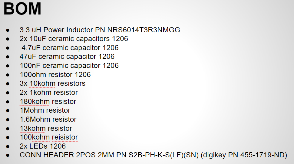
In this video series we build the ultimate battery circuit that can handle various battery chemistry's, charge batteries, perform load sharing during charging, handle input voltage levels that are higher or lower than the output, and more. In part 2 we will look at the PCB layout with a focus on the buck boost DC to DC Converter and look at the BOM.


Sunday, December 3, 2017

Ultimate Battery Circuit Design Part 1

In this video series we build the ultimate battery circuit that can handle various battery chemistry's, charge batteries, perform load sharing during charging, handle input voltage levels that are higher or lower than the output, and more. In part 1 we will look at the circuit configuration and component values that we plan to use.


Tuesday, February 4, 2014

Building a Wireless Temperature Sensor Network Part 3

Welcome back for part 3 of building a wireless temperature sensor network. In part 2 we started to build our sensor network and collect temperature data from multiple sensors. In this post (part 3) and continuing into the next post (part 4) we will look at some design options for powering our wireless sensors so we can spread them out to anywhere we need to monitor the temperature.

The two power source options we will consider for powering our wireless sensors are battery power and an AC line powered DC power supply. What I mean by “AC line powered DC power supply” is the low cost constant voltage power supplies that often come with consumer electronics or that can be bought standalone from places like Radio Shack. In the below picture is an example of low cost DC power supply that puts out a constant 12 VDC and up to 200 mA.


Before deciding on a power source, lets first cover the need for a voltage conversion stage in our sensor designs. Whether we use a power supply or a battery pack they probably will not output the exact voltage we need for the sensors, which is 5 V for the controller and approximately 3.3 V for the routers hence the need for a voltage conversion stage. For doing voltage conversion there are two main options available: voltage regulators and DC to DC converters. Each has their advantages and disadvantages. Voltage regulators are low cost and less complex, but are less efficient (more power loss in the conversion process). DC to DC converters are more efficient, but are more complex to implement and can be more expensive. Let me add explanation around the complexity of DC to DC converters. When you implement a DC to DC converter you need to add a lot of “supporting components” (resistors, capacitors, inductors) at the input and output of the DC to DC converter to have it operate correctly, which is beyond the scope of this post. But there is a way around it, some companies sell DC to DC converters with the “supporting components” already built-in. These DC to DC converters are easy to implement like voltage regulators, but still deliver great efficiency. Their downside is cost, they will easily be 5 or more times the price of a voltage regulator.

Which voltage conversion method you use in your design depends on factors such as power efficiency needs, budget, project time table. For instance, is power efficiency critical to your design? If your sensor needs to be battery powered and it is going to be located in a place where it can not be easily accessed than you probably want to go with a DC to DC converter. If your sensor will be near a power outlet or if changing the battery and recharging it is easy than the voltage regulator is a good choice. In this tutorial we will us both conversion methods for example purposes.

If you want to power your sensors using battery power the most common battery technologies for this task include alkaline, nickel metal hydride (NiMH), lithium ion (Li-ion), and lithium ion polymer (Li-ion polymer). Alkaline batteries are the ones you buy at the store for your TV remote or flashlight, they are typically not rechargeable. The other battery technologies listed above are rechargeable and have their advantages and disadvantages. Covering the details of each battery technology and their safety precautions is beyond the scope of this tutorial. Luckily there is plenty of information on the internet on these battery technologies and how to use them safely so if you plan to use batteries to power your sensor do your homework first. Especially if you want to use the Li-ion or Li-ion polymer technologies because they are the most dangerous. For this tutorial we will use two different battery technologies for example purposes, alkaline and Li-ion polymer.

Here is a breakdown of the power source and voltage conversion technique that will be used for each part of the wireless sensor network:
  • For the controller the Arduino Uno has a built-in voltage regulator at the power input connector that takes 7 to 12 VDC power source and converts it to 5 V to power the Uno. A 9 V DC power supply will be used to power the controller. The power supply was obtained from an old cordless phone.
  • For sensor 1 (XBee router with temperature sensor) we will use the LM317 voltage regulator for the conversion stage. This is a common low cost regulator that has an adjustable output voltage. You can find it at RadioShack. The datasheet, which you can easily find online, explains how to set the output voltage using basic components. For instructions on how I set the output voltage to 3.3 V for this project see the last section of this post. The power source we will use is a 7.4 volt Li-ion polymer rechargeable battery pack. 
  • For sensor 2 we will use the TSR12433 DC to DC converter that requires no external components, just plug in and go. This was $15 and it was purchased from Adafruit. The power source we will use is four series Alkaline batteries. You could easily get away with three series Alkaline batteries, four was used because I had a holder for four batteries.
What is nice about the XBee modules is they use very low power in general so with the power setups we are using we are going to get good battery life. Let's do some quick calculations to look at what kind of battery life we can expect with these two battery powered setups. To do this let's first look at the amp hour (abbreviated 'Ah') ratings of our two battery based power sources:
  1. The 7.4 V Li-ion Polymer is rated for 2200 mAh or 2.2 Ah.
  2. The Ah ratings for Alkaline batteries varies widely depending on the brand, a good rule of thumb is the higher the cost the more Ah you are getting. We will use the conservative estimate of 1500 mAh or 1.5 Ah for each battery so a total of 6000 mAh or 6 Ah
Next for our battery life calculation we need to know the average current consumption of sensor 1 and sensor 2. We need to know on average how much current does the XBee router, temperature sensor, and power conversion stage consume. To do this I measured the current consumption of each sensor design using an Agilent N6705B DC power analyzer. I am fortunate enough to have access to this device at work since it is out of the price range of most hobbyists. For sensor 1 the average current consumption was 15.59 mA, for simplicity we will round up to 16 mA. For sensor 2 the average current consumption was 6.58 mA, for simplicity we will round up to 7 mA. Please note that using the regulator more than doubles the current consumption of our sensor. This results in the following battery life calculations:
  1. Sensor 1 --> 2200 mAh / 16 mA = 137.5 hours of battery life or ~ 6 days
  2. Sensor 2 --> 6000 mAh / 7 mA = 857.1 hours of battery life or ~ 36 days
The lower current consumption of the DC to DC converter combined with the higher Ah rating of the Alkaline batteries results in ~ 6 times longer battery life for sensor 1 compared to sensor 2. This is the power design direction you would want to go with if your sensor is going to be used in an area that is not easy to access. The sensor 2's power design is a lower cost example since the regulator is cheap and you do not have to keep buying new batteries since the Li-ion Polymer is rechargeable. 

As a comparison of the sensor 1 and 2's current consumption compared to the controller's (sensor 3), the controller's average current consumption is 102.6 mA. As you can see the Arduino consumes quite a bit more power compared to the XBee. You can further increase the battery life of your sensors by using the "sleep" capabilities of the XBee modules. We will not be getting into the details of the sleep capabilities of the XBee modules in this project, but refer to the XBee manual for details on using the sleep capabilities. 

That is it for part 3 of building a wireless sensor network. We will see you back soon for part 4 where we will look at a schematic diagram of our sensors with the new power sections added, we will implement a way to know when our batteries need to be replaced, and make the needed changes to our Arduino code to accommodate these changes. 

Setting the output of the LM317 voltage regulator
The LM317 is a widely used low cost regulator. It is great part to keep in stock around you electronics lab bench since its output voltage level is adjustable so you can fit it into any project you are working on. It is made by a couple different manufacturers including Fairchild, you can find its data sheet by following the link: http://www.fairchildsemi.com/ds/LM/LM317.pdf. The figure below is from page 5 of the datasheet and it shows the circuit setup and equation to set the output voltage level to the value you desire.


From the above equation we need to solve for R2 because that is the unknown. Also since IADJ is so small we can just take the last term out of the equation. Solving for R2 and dropping out the last term we get:
R2 = (Vo*R1)/1.25 - R1. Now we just need to plug in our known values which are 3.3 V for Vo and for R1 I used a 301 Ohm resistor that was laying around. plugging in our values to the equation we get 494 Ohms for R2. To implement R2 a 1 kOhm adjustable resistor was used. The resistor was adjusted to about ~500 Ohms. I then connected its input to the battery and its output to the sensor. I used a DMM to measure the resulting output voltage of the regulator and fine tuned the resistor value to get exactly 3.3 VDC, the desired output voltage.