Showing posts with label ADC. Show all posts

Friday, May 31, 2019

Ways to Improve ADC Measurement Accuracy and Resolution Part 2

In part two of this 4 or 5 part series, we look at how the Successive Approximation or SAR ADC architecture works and understand its limitations. Note SAR based ADC architecture is what you typically find in microcontrollers.


To access the white paper that was referenced to derive the equation related to RC time constants and sampling time: https://www.silabs.com/documents/public/application-notes/AN119.pdf

Cutout from Silicon Labs App Note on calculating settling time for SAR ADC

Saturday, March 30, 2019

Ways to Improve ADC Measurement Accuracy and Resolution Part 1

In this video series we look at ways or tips to improve ADC measurement accuracy and resolution. In part 1 define what accuracy and resolution is and different types of error that can affect ADC measurements. We also look at the importance of using an accurate ADC reference voltage and why you want to scale the range of the signal you are measuring to the ADC's range.


//***************Arduino code used in video*******************************
/*This code demonstrates how to change the ADC voltage reference on an Arduino 
 * This was shown in an ADC tutorial on the ForceTronics YouTube Channel.
* This code is free and open for anybody to use at their own risk. 
*/

void setup() {
  Serial.begin(115200); //setup serial connection
  while(!Serial);
  analogReference(AR_EXTERNAL); //sets the ADC reference voltage to external (input is aRef pin)
  //analogReference(AR_DEFAULT); //set the ADC reference to default which is AVCC (uses power supply voltage or VCC as reference)
  //analogReference(AR_INTERNAL2V23); //uses 2.23V internal reference in SAMD21 uC
  analogReadResolution(12); //Set ADC to 12bit resolution, default is 10
  burn8Readings(); //make 8 readings but don't use them to ensure good reading after reference change
  delay(100);
  for(int i=0;i<500;i++) { //loop through a bunch of ADC readings and print them to serial plotter
    Serial.println(analogRead(A0)); //Make ADC measurement at A0
  }
  
}

void loop() {
  //don't need the loop
}

//This function makes 8 ADC measurements but does nothing with them
//Since after a reference change the ADC can return bad readings at first. This function is used to get rid of the first 
//8 readings to ensure an accurate one is displayed
void burn8Readings() {
  for(int i=0; i<8; i++) {
    analogRead(A0);
    delay(1);
  }
}

Friday, November 9, 2018

Designing a Thermocouple Temperature Measurement Circuit Part 2

In this series we look at how to design a Thermocouple temperature measurement circuit. In part 2 we look at a real world example of a Thermocouple J Type circuit design and discuss some of the common sources of error and how to avoid them.


Sunday, July 15, 2018

Speeding up the ADC on Arduino SAMD21 Boards (Zero, Mkr, etc) Part 2

In this video we look at how to get higher ADC speeds out of Arduino boards that are based off of the SAMD21 microcontroller. In part 2 we discuss memory limitations and we leverage an Adafruit library to do an FFT on the ADC data.


Link to details on PCBWay Maker Contest: ttps://www.pcbway.com/project/PCB_DESIGN_CONTEST.aspx

//*******************Arduino Code from Video*********************************
/*This code is from a tutorial on the ForceTronics YouTube Channel that talks about speeding up the sample rate on Arduino boards 
 * that use the SAMD21 microcontroller like the Arduino Zero or MKR series. This code is free and clear for other to use and modify 
 * at their own risk. 
 */
#include "Adafruit_ZeroFFT.h" //adafruit library for FFT
#include <SPI.h>
#include <SD.h>

const long sRate = 300000; //sample rate of ADC
const int16_t dSize = 1024; //used to set number of samples
const byte chipSelect = 38; //used for SPI chip select pin
const byte gClk = 3; //used to define which generic clock we will use for ADC
const byte intPri = 0; //used to set interrupt priority for ADC
const int cDiv = 1; //divide factor for generic clock
const float period = 3.3334; //period of 300k sample rate
String wFile = "ADC_DATA"; //used as file name to store wind and GPS data
volatile int16_t aDCVal[dSize]; //array to hold ADC samples
volatile int count = 0; //tracks how many samples we have collected
bool done = false; //tracks when done writing data to SD card

void setup() {
  portSetup(); //setup the ports or pin to make ADC measurement
  genericClockSetup(gClk,cDiv); //setup generic clock and routed it to ADC
  aDCSetup(); //this function set up registers for ADC, input argument sets ADC reference
  setUpInterrupt(intPri); //sets up interrupt for ADC and argument assigns priority
  aDCSWTrigger(); //trigger ADC to start free run mode
}

void loop() {
  
  if(count==(dSize-1) and !done) { //if done reading and they have not been written to SD card yet
    removeDCOffset(aDCVal, dSize, 8); //this function removes DC offset if you are measuring an AC signal
    int16_t fTTVal[dSize]; //array to hold FFT samples
    for(int j=0; j<dSize; j++) fTTVal[j] = aDCVal[j]; //copy one array to another array
    ZeroFFT(fTTVal,dSize); //calculate FFT and store into array
    SD.begin(chipSelect); //start SD card library
    File myFile = SD.open((wFile + ".csv"), FILE_WRITE); //open file to write data to CSV file
    if (myFile) {
      float sTime = 0;
      for (int y = 0; y < dSize; y++) { //write each reading to CSV 
        myFile.print(String(FFT_BIN(y, sRate, dSize))+",");
        myFile.print(String((fTTVal[y]))+",");
        myFile.print(sTime,5); //write each reading to SD card as string
        myFile.print(",");
        myFile.println(String(aDCVal[y])+","); //write each reading to SD card as string
        sTime = sTime + period; //update signal period info
      }
    }
    myFile.close(); //close file
    done = true; //we are done 
  }
}

//function for configuring ports or pins, note that this will not use the same pin numbering scheme as Arduino
void portSetup() {
  // Input pin for ADC Arduino A0/PA02
  REG_PORT_DIRCLR1 = PORT_PA02;

  // Enable multiplexing on PA02_AIN0 PA03/ADC_VREFA
  PORT->Group[0].PINCFG[2].bit.PMUXEN = 1;
  PORT->Group[0].PINCFG[3].bit.PMUXEN = 1;
  PORT->Group[0].PMUX[1].reg = PORT_PMUX_PMUXE_B | PORT_PMUX_PMUXO_B;
}

//this function sets up the generic clock that will be used for the ADC unit
//by default it uses the 48M system clock, input arguments set divide factor for generic clock and choose which generic clock
//Note unless you understand how the clock system works use clock 3. clocks 5 and up can brick the microcontroller based on how Arduino configures things
void genericClockSetup(int clk, int dFactor) {
  // Enable the APBC clock for the ADC
  REG_PM_APBCMASK |= PM_APBCMASK_ADC;
  
  //This allows you to setup a div factor for the selected clock certain clocks allow certain division factors: Generic clock generators 3 - 8 8 division factor bits - DIV[7:0]
  GCLK->GENDIV.reg |= GCLK_GENDIV_ID(clk)| GCLK_GENDIV_DIV(dFactor);
  while (GCLK->STATUS.reg & GCLK_STATUS_SYNCBUSY);  

  //configure the generator of the generic clock with 48MHz clock
  GCLK->GENCTRL.reg |= GCLK_GENCTRL_GENEN | GCLK_GENCTRL_SRC_DFLL48M | GCLK_GENCTRL_ID(clk); // GCLK_GENCTRL_DIVSEL don't need this, it makes divide based on power of two
  while (GCLK->STATUS.reg & GCLK_STATUS_SYNCBUSY);
  
  //enable clock, set gen clock number, and ID to where the clock goes (30 is ADC)
  GCLK->CLKCTRL.reg |= GCLK_CLKCTRL_CLKEN | GCLK_CLKCTRL_GEN(clk) | GCLK_CLKCTRL_ID(30);
  while (GCLK->STATUS.bit.SYNCBUSY);
}

/*
ADC_CTRLB_PRESCALER_DIV4_Val    0x0u  
ADC_CTRLB_PRESCALER_DIV8_Val    0x1u   
ADC_CTRLB_PRESCALER_DIV16_Val   0x2u   
ADC_CTRLB_PRESCALER_DIV32_Val   0x3u   
ADC_CTRLB_PRESCALER_DIV64_Val   0x4u   
ADC_CTRLB_PRESCALER_DIV128_Val  0x5u   
ADC_CTRLB_PRESCALER_DIV256_Val  0x6u   
ADC_CTRLB_PRESCALER_DIV512_Val  0x7u   
--> 8 bit ADC measurement takes 5 clock cycles, 10 bit ADC measurement takes 6 clock cycles
--> Using 48MHz system clock with division factor of 1
--> Using ADC division factor of 32
--> Sample rate = 48M / (5 x 32) = 300 KSPS
This function sets up the ADC, including setting resolution and ADC sample rate
*/
void aDCSetup() {
  // Select reference
  REG_ADC_REFCTRL = ADC_REFCTRL_REFSEL_INTVCC1; //set vref for ADC to VCC

  // Average control 1 sample, no right-shift
  REG_ADC_AVGCTRL |= ADC_AVGCTRL_SAMPLENUM_1;

  // Sampling time, no extra sampling half clock-cycles
  REG_ADC_SAMPCTRL = ADC_SAMPCTRL_SAMPLEN(0);
  
  // Input control and input scan
  REG_ADC_INPUTCTRL |= ADC_INPUTCTRL_GAIN_1X | ADC_INPUTCTRL_MUXNEG_GND | ADC_INPUTCTRL_MUXPOS_PIN0;
  // Wait for synchronization
  while (REG_ADC_STATUS & ADC_STATUS_SYNCBUSY);

  ADC->CTRLB.reg |= ADC_CTRLB_RESSEL_8BIT | ADC_CTRLB_PRESCALER_DIV32 | ADC_CTRLB_FREERUN; //This is where you set the divide factor, note that the divide call has no effect until you change Arduino wire.c
  //Wait for synchronization
  while (REG_ADC_STATUS & ADC_STATUS_SYNCBUSY);

  ADC->WINCTRL.reg = ADC_WINCTRL_WINMODE_DISABLE; // Disable window monitor mode
  while(ADC->STATUS.bit.SYNCBUSY);

  ADC->EVCTRL.reg |= ADC_EVCTRL_STARTEI; //start ADC when event occurs
  while (ADC->STATUS.bit.SYNCBUSY);

  ADC->CTRLA.reg |= ADC_CTRLA_ENABLE; //set ADC to run in standby
  while (ADC->STATUS.bit.SYNCBUSY);
}

//This function sets up an ADC interrupt that is triggered 
//when an ADC value is out of range of the window
//input argument is priority of interrupt (0 is highest priority)
void setUpInterrupt(byte priority) {
  
  ADC->INTENSET.reg |= ADC_INTENSET_RESRDY; // enable ADC ready interrupt
  while (ADC->STATUS.bit.SYNCBUSY);

  NVIC_EnableIRQ(ADC_IRQn); // enable ADC interrupts
  NVIC_SetPriority(ADC_IRQn, priority); //set priority of the interrupt
}

//software trigger to start ADC in free run
//in future could use this to set various ADC triggers
void aDCSWTrigger() {
  ADC->SWTRIG.reg |= ADC_SWTRIG_START;
}

//This ISR is called each time ADC makes a reading
void ADC_Handler() {
    if(count<1023) {
      aDCVal[count] = REG_ADC_RESULT;
      count++;
    }
    ADC->INTFLAG.reg = ADC_INTENSET_RESRDY; //Need to reset interrupt
}

//This function takes out DC offset of AC signal, it assumes that the offset brings signal to zero volts
//input arguments: array with measured points and bits of measurement
void removeDCOffset(volatile int16_t aDC[], int aSize, int bits) {
  int aSteps = pow(2,bits)/2; //get number of levels in ADC measurement and cut it in half
  for(int i=0; i<aSize; i++) {
    aDC[i] = aDC[i] - aSteps; //take out offset
  }
}

Saturday, June 30, 2018

Speeding up the ADC on Arduino SAMD21 Boards (Zero, Mkr, etc) P1

In this video we look at how to get higher ADC speeds out of Arduino boards that are based off of the SAMD21 microcontroller.


Windows file paths from video:
  • files that define register data structures: C:\Users\yourname\AppData\Local\Arduino15\packages\arduino\hardware\samd\1.6.18\bootloaders\sofia\Bootloader_D21_Sofia_V2.1\src\ASF\sam0\utils\cmsis\samd21\include\component
  • wire.c file path: C:\Users\yourname\AppData\Local\Arduino15\packages\arduino\hardware\samd\1.6.18\cores\arduino

//*******************Arduino example code from video*************************
/*This code is from a tutorial on the ForceTronics YouTube Channel that talks about speeding up the sample rate on Arduino boards 
 * that use the SAMD21 microcontroller like the Arduino Zero or MKR series. This code is free and clear for other to use and modify 
 * at their own risk. 
 */
#include <SPI.h>
#include <SD.h>

const int16_t dSize = 1024; //used to set number of samples
const byte chipSelect = 38; //used for SPI chip select pin
const byte gClk = 3; //used to define which generic clock we will use for ADC
const byte intPri = 0; //used to set interrupt priority for ADC
const int cDiv = 1; //divide factor for generic clock
const float period = 3.3334; //period of 300k sample rate
String wFile = "ADC_DATA"; //used as file name to store wind and GPS data
volatile int aDCVal[dSize]; //array to hold ADC samples
volatile int count = 0; //tracks how many samples we have collected
bool done = false; //tracks when done writing data to SD card

void setup() {
  portSetup(); //setup the ports or pin to make ADC measurement
  genericClockSetup(gClk,cDiv); //setup generic clock and routed it to ADC
  aDCSetup(); //this function set up registers for ADC, input argument sets ADC reference
  setUpInterrupt(intPri); //sets up interrupt for ADC and argument assigns priority
  aDCSWTrigger(); //trigger ADC to start free run mode
}

void loop() {
  
  if(count==(dSize-1) and !done) { //if done reading and they have not been written to SD card yet
    removeDCOffset(aDCVal, dSize, 8); //this function removes DC offset if you are measuring an AC signal
    SD.begin(chipSelect); //start SD card library
    File myFile = SD.open((wFile + ".csv"), FILE_WRITE); //open file to write data to CSV file
    if (myFile) {
      float sTime = 0;
      for (int y = 0; y < dSize; y++) {
        myFile.print(sTime,5); //write each reading to SD card as string
        myFile.print(",");
        myFile.println(String(aDCVal[y])+","); //write each reading to SD card as string
        sTime = sTime + period; //update signal period info
      }
    }
    myFile.close(); //close file
    done = true; //we are done 
  }
}

//function for configuring ports or pins, note that this will not use the same pin numbering scheme as Arduino
void portSetup() {
  // Input pin for ADC Arduino A0/PA02
  REG_PORT_DIRCLR1 = PORT_PA02;

  // Enable multiplexing on PA02_AIN0 PA03/ADC_VREFA
  PORT->Group[0].PINCFG[2].bit.PMUXEN = 1;
  PORT->Group[0].PINCFG[3].bit.PMUXEN = 1;
  PORT->Group[0].PMUX[1].reg = PORT_PMUX_PMUXE_B | PORT_PMUX_PMUXO_B;
}

//this function sets up the generic clock that will be used for the ADC unit
//by default it uses the 48M system clock, input arguments set divide factor for generic clock and choose which generic clock
//Note unless you understand how the clock system works use clock 3. clocks 5 and up can brick the microcontroller based on how Arduino configures things
void genericClockSetup(int clk, int dFactor) {
  // Enable the APBC clock for the ADC
  REG_PM_APBCMASK |= PM_APBCMASK_ADC;
  
  //This allows you to setup a div factor for the selected clock certain clocks allow certain division factors: Generic clock generators 3 - 8 8 division factor bits - DIV[7:0]
  GCLK->GENDIV.reg |= GCLK_GENDIV_ID(clk)| GCLK_GENDIV_DIV(dFactor);
  while (GCLK->STATUS.reg & GCLK_STATUS_SYNCBUSY);  

  //configure the generator of the generic clock with 48MHz clock
  GCLK->GENCTRL.reg |= GCLK_GENCTRL_GENEN | GCLK_GENCTRL_SRC_DFLL48M | GCLK_GENCTRL_ID(clk); // GCLK_GENCTRL_DIVSEL don't need this, it makes divide based on power of two
  while (GCLK->STATUS.reg & GCLK_STATUS_SYNCBUSY);
  
  //enable clock, set gen clock number, and ID to where the clock goes (30 is ADC)
  GCLK->CLKCTRL.reg |= GCLK_CLKCTRL_CLKEN | GCLK_CLKCTRL_GEN(clk) | GCLK_CLKCTRL_ID(30);
  while (GCLK->STATUS.bit.SYNCBUSY);
}

/*
ADC_CTRLB_PRESCALER_DIV4_Val    0x0u  
ADC_CTRLB_PRESCALER_DIV8_Val    0x1u   
ADC_CTRLB_PRESCALER_DIV16_Val   0x2u   
ADC_CTRLB_PRESCALER_DIV32_Val   0x3u   
ADC_CTRLB_PRESCALER_DIV64_Val   0x4u   
ADC_CTRLB_PRESCALER_DIV128_Val  0x5u   
ADC_CTRLB_PRESCALER_DIV256_Val  0x6u   
ADC_CTRLB_PRESCALER_DIV512_Val  0x7u   
--> 8 bit ADC measurement takes 5 clock cycles, 10 bit ADC measurement takes 6 clock cycles
--> Using 48MHz system clock with division factor of 1
--> Using ADC division factor of 32
--> Sample rate = 48M / (5 x 32) = 300 KSPS
This function sets up the ADC, including setting resolution and ADC sample rate
*/
void aDCSetup() {
  // Select reference
  REG_ADC_REFCTRL = ADC_REFCTRL_REFSEL_INTVCC1; //set vref for ADC to VCC

  // Average control 1 sample, no right-shift
  REG_ADC_AVGCTRL |= ADC_AVGCTRL_SAMPLENUM_1;

  // Sampling time, no extra sampling half clock-cycles
  REG_ADC_SAMPCTRL = ADC_SAMPCTRL_SAMPLEN(0);
  
  // Input control and input scan
  REG_ADC_INPUTCTRL |= ADC_INPUTCTRL_GAIN_1X | ADC_INPUTCTRL_MUXNEG_GND | ADC_INPUTCTRL_MUXPOS_PIN0;
  // Wait for synchronization
  while (REG_ADC_STATUS & ADC_STATUS_SYNCBUSY);

  ADC->CTRLB.reg |= ADC_CTRLB_RESSEL_8BIT | ADC_CTRLB_PRESCALER_DIV32 | ADC_CTRLB_FREERUN; //This is where you set the divide factor, note that the divide call has no effect until you change Arduino wire.c
  //Wait for synchronization
  while (REG_ADC_STATUS & ADC_STATUS_SYNCBUSY);

  ADC->WINCTRL.reg = ADC_WINCTRL_WINMODE_DISABLE; // Disable window monitor mode
  while(ADC->STATUS.bit.SYNCBUSY);

  ADC->EVCTRL.reg |= ADC_EVCTRL_STARTEI; //start ADC when event occurs
  while (ADC->STATUS.bit.SYNCBUSY);

  ADC->CTRLA.reg |= ADC_CTRLA_ENABLE; //set ADC to run in standby
  while (ADC->STATUS.bit.SYNCBUSY);
}

//This function sets up an ADC interrupt that is triggered 
//when an ADC value is out of range of the window
//input argument is priority of interrupt (0 is highest priority)
void setUpInterrupt(byte priority) {
  
  ADC->INTENSET.reg |= ADC_INTENSET_RESRDY; // enable ADC ready interrupt
  while (ADC->STATUS.bit.SYNCBUSY);

  NVIC_EnableIRQ(ADC_IRQn); // enable ADC interrupts
  NVIC_SetPriority(ADC_IRQn, priority); //set priority of the interrupt
}

//software trigger to start ADC in free run
//in future could use this to set various ADC triggers
void aDCSWTrigger() {
  ADC->SWTRIG.reg |= ADC_SWTRIG_START;
}

//This ISR is called each time ADC makes a reading
void ADC_Handler() {
    if(count<1023) {
      aDCVal[count] = REG_ADC_RESULT;
      count++;
    }
    ADC->INTFLAG.reg = ADC_INTENSET_RESRDY; //Need to reset interrupt
}

//This function takes out DC offset of AC signal, it assumes that the offset brings signal to zero volts
//input arguments: array with measured points and bits of measurement
void removeDCOffset(volatile int aDC[], int aSize, int bits) {
  int aSteps = pow(2,bits)/2; //get number of levels in ADC measurement and cut it in half
  for(int i=0; i<aSize; i++) {
    aDC[i] = aDC[i] - aSteps; //take out offset
  }
}

Monday, April 9, 2018

Ground Considerations for PCB Layout of Mixed Signal Designs Part 2

In this video series we look at considerations when laying out a ground plane on a PCB when working with a mixed signal designs. If you want to ensure you are making accurate noise free ADC measurements in your design this video series is a must watch.


Reference material:
Partitioning and Layout of a Mixed-Signal PCB http://www.hottconsultants.com/pdf_files/june2001pcd_mixedsignal.pdf

Grounding in mixed-signal systems demystified, Part 1 and 2
http://www.ti.com/lit/an/slyt499/slyt499.pdf
http://www.ti.com/lit/an/slyt512/slyt512.pdf

Tuesday, April 3, 2018

Ground Considerations for PCB Layout of Mixed Signal Designs Part 1

In this video we look at considerations when laying out a ground plane on a PCB when working with a mixed signal designs. If you want to ensure you are making accurate noise free ADC measurements in your design this video series is a must watch.


Partitioning and Layout of a Mixed-Signal PCB http://www.hottconsultants.com/pdf_files/june2001pcd_mixedsignal.pdf

Sunday, April 30, 2017

Building a Custom Strain Gauge with Electric Paint

In this video we look at how we can use Bare Conductive's Electric Paint to create a custom strain gauge.


/*
 * This code was written for a video on the ForceTronics YouTube channel. This code is public domain and can be used and modified by anybody at your own risk
 */

#include <Average.h> //Call average library

void setup() {
  Serial.begin(57600);
  analogReadResolution(12); //Set Arduino Zero ADC to 12 bits
  for(int i=0;i<4;i++) analogRead(A0); //burn a couple readings since we changed ADC setting
  Average<int> ave(10);
}

void loop() {
  delay(100);
  Average<int> ave(10); //Create average object
  for (int i=0; i<10;i++) ave.push(analogRead(A0) - 2700); //get 10 readings and subtract most of the value off to look at small changes
  Serial.println(ave.mean()); //average the 10 readings together
}

Sunday, March 5, 2017

Reduce Noise in Your Sensor Measurements with an Active Low Pass Filter Part 2

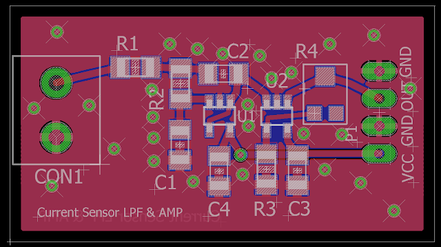
In this three part series we look at how to design a signal conditioning circuit to increase the accuracy and resolution of your ADC measurements. The signal conditioning circuit consists of a double pole active Sallen Key Low Pass Filter and a non-inverting op amp. The filter portion is meant to attenuate high frequency noise from your sensor signal to increase measurement accuracy. The amplifier portion scales the signal up to the full range of the ADC to ensure you are getting max resolution. In part 2 we do the PCB layout of our circuit using Eagle CAD software.


You can access the Eagle files on Github at: https://github.com/ForceTronics/Sallen-Key-Low-Pass-Filter-Design/tree/master


Monday, February 27, 2017

Reduce Noise in Your Sensor Measurements with an Active Low Pass Filter Part 1

In this three part series we look at how to design a signal conditioning circuit to increase the accuracy and resolution of your ADC measurements. The signal conditioning circuit consists of a double pole active Sallen Key Low Pass Filter and a non-inverting op amp. The filter portion is meant to attenuate high frequency noise from your sensor signal to increase measurement accuracy. The amplifier portion scales the signal up to the full range of the ADC to ensure you are getting max resolution.


You can find the online filter calculator used in part one at this link: http://sim.okawa-denshi.jp/en/OPseikiLowkeisan.htmk

You can access the LTspice file on Github at: https://github.com/ForceTronics/Sallen-Key-Low-Pass-Filter-Design/tree/master

Sallen-Key Low Pass Filter Circuit with Amplifier Stage in LTspice

Friday, October 14, 2016

Utilizing Advanced ADC Capabilities on Arduino’s with the SAMD21 (Zero, MKR1000, etc) Part 1

We are all familiar with the Arduino "analogRead()" function, but there is a lot more to the SAMD21 ADC then just taking simple readings. In this video series we look at some of the more advanced ADC capabilities of the SAMD21 and how to use them. In part 1 we look at how to use the window monitoring capability of the ADC.


//*******************Arduino code from the video*********************
//This sketch is from a tutorial on the ForceTronics YouTube Channel called 
//Utilizing Advanced ADC Capabilities on Arduino’s with the SAMD21 (Zero, MKR1000, etc)
//This code is public domain and free to anyone to use or modify at your own risk

//declare const for window mode settings
const byte DISABLE = 0;
const byte MODE1 = 1;
const byte MODE2 = 2;
const byte MODE3 = 3;
const byte MODE4 = 4;

void setup() {
  //call this function to start the ADC in window and define the window parameters
  ADCWindowBegin(MODE1, 512, 750); //Do not use the Arduino analog functions until you call ADCWindowEnd()
  Serial.begin(57600);
}

void loop() {
  delay(1500);
  Serial.println(readADC()); //the "readADC()" function can be used to get ADC readings while in Window mode
  Serial.println();
}

//This is the interrupt service routine (ISR) that is called 
//if an ADC measurement falls out of the range of the window 
void ADC_Handler() {
    digitalWrite(LED_BUILTIN, HIGH); //turn LED off
    ADC->INTFLAG.reg = ADC_INTFLAG_WINMON; //Need to reset interrupt
}

//this function sets up the ADC window mode with interrupt
void ADCWindowBegin(byte mode, int upper, int lower) {
  setMeasPin(); //function sets up ADC pin A0 as input
  setGenClock(); //setup ADC clock, using internal 8MHz clock
  setUPADC(); //configure ADC
  setADCWindow(mode, upper, lower); //setup ADC window mode 
  setUpInterrupt(0); //setup window mode interrupt with highest priority
  enableADC(1); //enable ADC 
}

void ADCWindowEnd() {
  NVIC_DisableIRQ(ADC_IRQn); //turn off interrupt
  enableADC(0); //disable ADC 
}

//setup measurement pin, using Arduino ADC pin A3
void setMeasPin() {
  // Input pin for ADC Arduino A3/PA04
  REG_PORT_DIRCLR1 = PORT_PA04;

  // Enable multiplexing on PA04
  PORT->Group[0].PINCFG[4].bit.PMUXEN = 1;
  PORT->Group[0].PMUX[1].reg = PORT_PMUX_PMUXE_B | PORT_PMUX_PMUXO_B;
}

//Function sets up generic clock for ADC
//Uses built-in 8MHz clock
void setGenClock() {
   // Enable the APBC clock for the ADC
  REG_PM_APBCMASK |= PM_APBCMASK_ADC;

  configOSC8M(); //this function sets up the internal 8MHz clock that we will use for the ADC
  
  // Setup clock GCLK3 for no div factor
   GCLK->GENDIV.reg |= GCLK_GENDIV_ID(3)| GCLK_GENDIV_DIV(1);
   while (GCLK->STATUS.reg & GCLK_STATUS_SYNCBUSY);  

  //configure the generator of the generic clock, which is 8MHz clock
  GCLK->GENCTRL.reg |= GCLK_GENCTRL_GENEN | GCLK_GENCTRL_SRC_OSC8M | GCLK_GENCTRL_ID(3) | GCLK_GENCTRL_DIVSEL;
  while (GCLK->STATUS.reg & GCLK_STATUS_SYNCBUSY);
  
  //enable clock, set gen clock number, and ID to where the clock goes (30 is ADC)
  GCLK->CLKCTRL.reg |= GCLK_CLKCTRL_CLKEN | GCLK_CLKCTRL_GEN(3) | GCLK_CLKCTRL_ID(30);
  while (GCLK->STATUS.bit.SYNCBUSY);
}

//Function that does general settings for ADC
//sets it for a single sample
//Uses internal voltage reference
//sets gain factor to 1/2
void setUPADC() {
  // Select reference, internal VCC/2
  ADC->REFCTRL.reg |= ADC_REFCTRL_REFSEL_INTVCC1; // VDDANA/2, combine with gain DIV2 for full VCC range

  // Average control 1 sample, no right-shift
  ADC->AVGCTRL.reg |= ADC_AVGCTRL_ADJRES(0) | ADC_AVGCTRL_SAMPLENUM_1;

  // Sampling time, no extra sampling half clock-cycles
  REG_ADC_SAMPCTRL |= ADC_SAMPCTRL_SAMPLEN(0);

  // Input control: set gain to div by two so ADC has measurement range of VCC, no diff measurement so set neg to gnd, pos input set to pin 0 or A0
  ADC->INPUTCTRL.reg |= ADC_INPUTCTRL_GAIN_DIV2 | ADC_INPUTCTRL_MUXNEG_GND | ADC_INPUTCTRL_MUXPOS_PIN4;
  while (REG_ADC_STATUS & ADC_STATUS_SYNCBUSY);

  // PS16, 8 MHz, ADC_CLK = 500 kHz, ADC sampling rate, single eded, 12 bit, free running, DIV2 gain, 7 ADC_CLKs, 14 usec
  ADC->CTRLB.reg |= ADC_CTRLB_PRESCALER_DIV16 | ADC_CTRLB_RESSEL_10BIT | ADC_CTRLB_FREERUN; // Run ADC continously, 7 ADC_CLKs, 14 usec
  while (REG_ADC_STATUS & ADC_STATUS_SYNCBUSY);
}

//This function is used to setup the ADC windowing mode
//inputs are the mode, upper window value, and lower window value
//
void setADCWindow(byte mode, int upper, int lower) {
  ADC->WINCTRL.reg = mode; //set window mode
  while (ADC->STATUS.bit.SYNCBUSY);

   ADC->WINUT.reg = upper; //set upper threshold
   while (ADC->STATUS.bit.SYNCBUSY);

   ADC->WINLT.reg = lower; //set lower threshold
   while (ADC->STATUS.bit.SYNCBUSY);
}

//This function sets up an ADC interrupt that is triggered 
//when an ADC value is out of range of the window
//input argument is priority of interrupt (0 is highest priority)
void setUpInterrupt(byte priority) {
  
  ADC->INTENSET.reg |= ADC_INTENSET_WINMON; // enable ADC window monitor interrupt
   while (ADC->STATUS.bit.SYNCBUSY);

   NVIC_EnableIRQ(ADC_IRQn); // enable ADC interrupts
   NVIC_SetPriority(ADC_IRQn, priority); //set priority of the interrupt
}

//function allows you to enable or disable ADC
void enableADC(bool en) {
  if(en) ADC->CTRLA.reg = 2; //2 is binary 010 which is register bit to enable ADC
  else ADC->CTRLA.reg = 0; //0 disables ADC
}

//This function will return the latest ADC reading made during free run window mode
//must first start the ADC before calling this function
unsigned int readADC() {
  // Free running, wait for conversion to complete
  while (!(REG_ADC_INTFLAG & ADC_INTFLAG_RESRDY));
  // Wait for synchronization before reading RESULT
  while (REG_ADC_STATUS & ADC_STATUS_SYNCBUSY);
  
  return REG_ADC_RESULT;
}

//function enables the 8MHz clock used for the ADC
void configOSC8M() 
{
  SYSCTRL->OSC8M.reg |= SYSCTRL_OSC8M_ENABLE;
}


Wednesday, January 27, 2016

Utilizing the Arduino ADC Internal Reference

In this video we look at the ADC internal reference in an Arduino, why / when would you use it, how to ensure you get good measurement accuracy when using it, and how to use it to check your battery voltage.


**********************Arduino Code from the video****************************
float iREF = 1.08; //internal reference cal factor

void setup() {
  // put your setup code here, to run once:
  analogReference(EXTERNAL);
  //burn some ADC readings after reference change
  for(int i=0; i<8; i++) analogRead(A0);
  Serial.begin(57600);
}

void loop() {
  // put your main code here, to run repeatedly:
  delay(3000);
  Serial.print("Measured battery voltage is: ");
  Serial.println(fReadVcc());
  Serial.println();
}

//This function uses the known internal reference value of the 328p (~1.1V) to calculate the VCC value which comes from a battery
//This was leveraged from a great tutorial found at https://code.google.com/p/tinkerit/wiki/SecretVoltmeter?pageId=110412607001051797704
float fReadVcc() {
  ADMUX = _BV(REFS0) | _BV(MUX3) | _BV(MUX2) | _BV(MUX1);
  delay(3); //delay for 3 milliseconds
  ADCSRA |= _BV(ADSC); // Start ADC conversion
  while (bit_is_set(ADCSRA,ADSC)); //wait until conversion is complete
  int result = ADCL; //get first half of result
  result |= ADCH<<8; //get rest of the result
  float batVolt = (iREF / result)*1024; //Use the known iRef to calculate battery voltage
  return batVolt;
}

Wednesday, January 21, 2015

Maximizing Arduino’s ADC Resolution and Accuracy Part 3

In part three we look at the three main sources of error in an ADC measurement. We will discuss how to reduce total ADC error and how to quantify the total error of an ADC measurement.


Sunday, January 11, 2015

Maximizing Arduino’s ADC Resolution and Accuracy Part 2

In part 2 we will look at how to increase the accuracy of our ADC measurements using the built-in Noise Reduction Mode


Arduino Code********************************************************************
/*This example sketch shows how to make ADC measurements via registers and how to use the low noise or noise cancellation ADC measurement capability. 
This was shown in an ADC tutorial on the ForceTronics YouTube Channel.
This code is free and open for anybody to use at their own risk. 1/9/15
*/
#include <avr/sleep.h>

int normADC[10]; //Create an arrray to hold the "normal" or non-low noise ADC measurements
int lowNoiseADC[10]; //Create an array to hold the low noise ADC measurements

int const aVCC = 0b01000000; //variable to set ADC to use VCC as reference
int const iREF = 0b11000000; //variable to set ADC to use internal 1.1V as reference
int const aREF = 0b00000000; //variable to set ADC to use VCC as reference
//bits 7 and 6 select the ADC reference source
//The four zeros (bits 3 thru 0) at the end of the above binary register values sets the analog channel to A0
//Bit 5 selects right adjust for the result and bit 4 is not used

//Setup code only run once
void setup() {
  ADMUX = aVCC; //Configure the ADC via the ADMUX register for VCC as reference, result right adjust, and source A0 pin
  ADCSRA |= 1<<ADEN; //Turn the ADC on by setting the ADEN bit to 1 in the ADCSRA register
  ADCSRA |= 1<<ADIE; //Setting the ADIE bit to 1 means when the ADC is done a measurement it generates an interrupt, the interrupt will wake the chip up from low noise sleep
  ADCSRA |= ((1<<ADPS2)|(1<<ADPS1)|(1<<ADPS0));    //Prescaler at 128 so we have an 125Khz clock source
  //The ADC clock must be between 50kHz and 200kHz, since the Uno clock is 16MHz we want to divide it by 128 to get 125kHz. This may need to be adjusted for other Arduino boards
  //We do not have to use registers to set the sleep mode since we are using the avr/sleep.h library
  sleep_enable(); //enable the sleep capability
  set_sleep_mode(SLEEP_MODE_ADC); //set the type of sleep mode. We are using the ADC noise reduction sleep mode
  //Note that in this sleep mode the chip automatically starts an ADC measurement once the chip enters sleep mode
  //Note that the reason for making the ADC measurements and storing in arrays was to avoid using the arduino serial functions with sleep mode since serial uses interrupts
  for(int i=0; i<10; i++) { //Loop ten times and make ten ADC measurements in low noise mode
    sei(); //enable interrupts
    sleep_cpu(); //enter low ADC noise sleep mode, this action turns off certain clocks and other modules in the chip so they do not generate noise that affects the accuracy of the ADC measurement
    //The chip remains in sleep mode until the ADC measurement is complete and executes an interrupt which wakes the chip from sleep
    lowNoiseADC[i] = ADC; //get ADC result and store it in low noise measurement array
  }
  
  for(int k=0; k<10; k++) { //loop executes 10 times and makes 10 normal ADC measurements
    ADCSRA |= 1<<ADSC; //this bit starts conversion. It will remain high until conversion is complete
    while(ADCSRA & (1<<ADSC)) { delay(1);} //When ADSC bit goes low conversion is done
    normADC[k] = ADC; //get ADC result and store it in normal ADC measurement array
  }
  
  Serial.begin(9600); //Start serial comm to print out results to serial monitor
  while(!Serial.available()) { delay(1); } //wait to print out results until serial monitor is open and any character is sent
  Serial.println("Noise reduction:"); //labels the readings being printed
  for(int j=0; j<10;j++) { //loop ten times to print out all the low noise measurement in array
    Serial.println(convertToVolt(lowNoiseADC[j]),3); //Convert each low noise measurement to a voltage level and send it over serial with three decimal places precision
  }
  Serial.println(); //print a line feed
  Serial.println("No noise reduction:"); //print heading for normal ADC measurements
  for(int l=0; l<10;l++) { //loop ten times and print each ADC reading
    Serial.println(convertToVolt(normADC[l]),3); //Convert each normal ADC measurement to a voltage level and send it over serial with three decimal places precision
  }
}

void loop() {
 //do nothing in the loop
}

//This function takes the ADC integer value and turns it into a voltage level. The input is the measured ADC value.
float convertToVolt(int aVAL) {
  float refVal = 5.01;  //hard coded in AVCC value, measured the real value for higher accuracy
  return (((float)aVAL/1023)*refVal); //formula to convert ADC value to voltage reading
}

//this is the interrupt service routine for the ADC interrupt. This must be in the code for the interrupt to work correctly
ISR(ADC_vect) {
}

Wednesday, January 7, 2015

Maximizing Arduino’s ADC Resolution and Accuracy Part 1

In part 1, of this 3 to 4 part series, we will look at what ADC measurement resolution is and how to maximize it on the Arduino. We will also look at a simple hint to increase Arduino's ADC measurement accuracy. In later parts we will get much deeper into accuracy and how to increase it.


Arduino Code using analogreference()*************************************************
/*This example sketch shows how to change the reference for Arduino's ADC to default or internal 1.1V.
This sketch was used to show the measurement resolution advantage of scaling Arduino's ADC reference to 
the voltage range or scale being measured. This was shown in an ADC tutorial on the ForceTronics YouTube Channel.
This code is free and open for anybody to use at their own risk. 1/6/15
*/
float const aVCC = 5.049; //Actual measured voltage value at AVCC pin. This is im
float const iREF = 1.084; //Actual measured voltage value of the internal 1.1V reference
//Note that these values can be measured at the AREF pin

void setup() {
  Serial.begin(9600); //setup serial connection
}

void loop() {
  
  delay(1000); //delay 1 second between each ADC measurement
  analogReference(DEFAULT); //set the ADC reference to default which is AVCC (uses power supply voltage or VCC as reference)
  burn8Readings(); //make 8 readings but don't use them to ensure good reading after reference change
  Serial.println("Default (AVCC) Ref:");
  Serial.println(convertToVolt(aVCC,analogRead(A0)),3); //Make ADC measurement at A0, convert it to a voltage value, write value to serial with 3 decimal places 
  Serial.println(" ");
  delay(1000); //delay 1 second between each ADC measurement
  analogReference(INTERNAL); //set the ADC reference to internal 1.1V reference
  burn8Readings(); //make 8 readings but don't use them to ensure good reading after reference change
  Serial.println("Internal 1.1V Ref:");
  Serial.println(convertToVolt(iREF,analogRead(A0)),3); //Make ADC measurement at A0, convert it to a voltage value, write value to serial with 3 decimal places
  Serial.println(" ");
}

//This function makes 8 ADC measurements but does nothing with them
//Since after a reference change the ADC can return bad readings at first. This function is used to get rid of the first 
//8 readings to ensure an accurate one is displayed
void burn8Readings() {
  for(int i=0; i<8; i++) {
    analogRead(A0);
    delay(1);
  }
}

//This function convers the ADC level integer value into a useful voltage value.
//The inputs are the measured ADC value and the ADC reference voltage level
//The formula used was obtained from the data sheet: (ADC value / 1024) x ref voltage
float convertToVolt(float refVal, int aVAL) {
  return (((float)aVAL/1024)*refVal);
}

Arduino Code using Registers*************************************************
/*This example sketch shows how to change the reference for Arduino's ADC to default or internal 1.1V using registers.
This sketch was used to show the measurement resolution advantage of scaling Arduino's ADC reference to 
the voltage range or scale being measured. This was shown in an ADC tutorial on the ForceTronics YouTube Channel.
This code is free and open for anybody to use at their own risk. 1/6/15
*/

int const aVCC = 0b01000000; //variable to set ADC to use VCC as reference
int const iREF = 0b11000000; //variable to set ADC to use internal 1.1V as reference
int const aREF = 0b00000000; //variable to set ADC to use VCC as reference
//The three zeros at the end of the above binary register values sets the analog channel to A0

void setup() {
  Serial.begin(9600);
  ADCSRA |= 1<<ADEN; //Turn on ADC
  ADCSRA |= ((1<<ADPS2)|(1<<ADPS1)|(1<<ADPS0));    //Prescaler at 128 so we have an 125Khz clock source
}

void loop() {
  delay(1000);
  Serial.println("Internal Ref:");
  burn8Readings(iREF);
  Serial.println(measADC(iREF),3);
  Serial.println(" ");
  delay(1000);
  Serial.println("AVCC Ref:");
  burn8Readings(aVCC);
  Serial.println(measADC(aVCC),3);
  Serial.println(" ");
}

//This function makes an ADC measurement using registers
float measADC(int ref) {
  ADMUX =  ref; //bits 7&6 select reference, bit 5 R or L adjust (0 R), bit 4 unused, 3:0 is channel select (0000 is ADC0)
  //ADMUX |=  0b00000000; //bits 7&6 select reference, bit 5 R or L adjust (0 R), bit 4 unused, 3:0 is channel select (0000 is ADC0)
  ADCSRA |= 1<<ADSC; //this bit starts conversion. It will remain high until conversion is complete
  
  while(ADCSRA & (1<<ADSC)) { delay(1);} //ADIF bit goes high when conversion is complete and result is in ADCL and ADCH
  return convertToVolt(ref, ADC);
}

//This function takes the ADC integer value and turns it into a voltage level. The inputs are
//the selected reference source and the measured ADC value.
float convertToVolt(int refSet, int aVAL) {
  float refVal;
  if (refSet == iREF) { refVal = 1.08; } //hard coded in reference value for internal
  else { refVal = 5.05; } //hard coded in AVCC value
  
  return (((float)aVAL/1023)*refVal);
}

//This function makes 8 ADC measurements but does nothing with them
//Since after a reference change the ADC can return bad readings at first. 
//This function is used to get rid of the first 
//8 readings to ensure an accurate one is displayed
void burn8Readings(int ref) {
 for(int i = 0; i<8; i++) {
  measADC(ref);
  delay(1);
 } 
}