Showing posts with label op amp. Show all posts

Wednesday, March 6, 2019

Tutorial on Digital to Analog Converters (DAC) and Example Using the MCP4728 Part 2

Two part tutorial on digital to analog converters (DAC). In part 2 we take a look at the capabilities of the MCP4728 which is a four channel DAC controlled via I2C. See the links below to access the code and get the PCB design from the video at PCBWay.


Link for PCB board at PCBWay: https://www.pcbway.com/project/shareproject/W08904ASW106_DAC_Example_Gerber.html

//**********Arduino Code with MCP4728 examples from video***************
/*
 * This code was written to demonstrate functions on the MCP4728 4 channel DAC for a video on the ForceTronics YouTube channel
 * This sketch leverages a library from GitHub made by Hideakitai, link to library: https://github.com/hideakitai/MCP4728
 * This code is public domain and free to anyone to use and modify with no restrictions at your own risk
 */

#include <Wire.h>
#include "MCP4728.h"

MCP4728 dac; //create object to library
//variables for wavform
int const sampleCount = 24; //samples to read to have a buffer
int signalSamples[sampleCount]; //create array to hold signal or waveform
float pi2 = 6.283; //value of pi times 2
const long clkFrequency = 400000; //I2C clock frequency
const uint8_t t1 = 3; //pin to setup test 1 fast sinewave
const uint8_t t2 = 4; //pin to setup test 2 sync'd sinewaves
const uint8_t LDAC = 5; //Output pin on MCU to control LDAC(not) pin on DAC

void setup() {
 //Create sinewave
 float in;
 float hBit = 2047.5;
 for (int i=0;i<sampleCount;i++)
 {
   in = pi2*(1/(float)sampleCount)*(float)i;
   signalSamples[i] = (int)(sin(in)*hBit + hBit);
 }

 pinMode(t1,INPUT_PULLUP); //configure test check pins
 pinMode(t2,INPUT_PULLUP); //configure test check pins
 pinMode(LDAC,OUTPUT); //configure test check pins
 digitalWrite(LDAC,HIGH); //turn DAC outputs off
 Wire.begin(); //start up I2C library
 Wire.setClock(clkFrequency); //set clock frequency for I2C comm
 dac.attatch(Wire, 13); //second argument is Arduino pin connected to LDAC(not), we are controlling LDAC manually so just entered pin we are not using
 dac.readRegisters(); //Used to read current settings from MCP4728
 dac.selectVref(MCP4728::VREF::VDD, MCP4728::VREF::VDD, MCP4728::VREF::VDD, MCP4728::VREF::VDD); //setup voltage ref for each DAC channel
 dac.selectPowerDown(MCP4728::PWR_DOWN::NORMAL, MCP4728::PWR_DOWN::NORMAL, MCP4728::PWR_DOWN::NORMAL, MCP4728::PWR_DOWN::NORMAL); //set power down mode, used for saving power
 dac.selectGain(MCP4728::GAIN::X1, MCP4728::GAIN::X1, MCP4728::GAIN::X1, MCP4728::GAIN::X1); //set gain on output amp
 //dac.enable(true); //enables the DAC outputs by controlling LDAC pin, but we are controlling LDAC manually in this example

  //perform test one
  if(!digitalRead(t1)) {
    digitalWrite(LDAC,LOW);
    //output sinewave as fast as we can
    for(;;) { //run test for infinitity 
      for(int j=0;j<sampleCount;j++) {
        dac.analogWrite(MCP4728::DAC_CH::A,signalSamples[j]);
      }
    }
  }
  else { //perform test 2 
    for(;;) {  //run test for infinitity 
      for(int j=0;j<sampleCount;j++) {
        int temp = j;
        digitalWrite(LDAC,HIGH); //turn outputs off
       // delay(1);
        dac.analogWrite(MCP4728::DAC_CH::A,signalSamples[temp]);
        temp += 8; //shift sigal 90 degrees
        if(temp > 23) temp -= sampleCount;
        dac.analogWrite(MCP4728::DAC_CH::B,signalSamples[temp]);
        temp += 8; //shift sigal 90 degrees
        if(temp > 23) temp -= sampleCount;
        dac.analogWrite(MCP4728::DAC_CH::C,signalSamples[temp]);
        temp += 8; //shift sigal 90 degrees
        if(temp > 23) temp -= sampleCount;
        dac.analogWrite(MCP4728::DAC_CH::D,signalSamples[temp]);
        digitalWrite(LDAC,LOW); //turn outputs on all four outputs at same time
       // delay(1);
      }
    }
  }
}

void loop() {
}


Friday, November 9, 2018

Designing a Thermocouple Temperature Measurement Circuit Part 2

In this series we look at how to design a Thermocouple temperature measurement circuit. In part 2 we look at a real world example of a Thermocouple J Type circuit design and discuss some of the common sources of error and how to avoid them.


Wednesday, March 22, 2017

Reduce Noise in Your Sensor Measurements with an Active Low Pass Filter Part 3

In this three part series we look at how to design a signal conditioning circuit to increase the accuracy and resolution of your ADC sensor measurements. The signal conditioning circuit consists of a double pole active Sallen Key Low Pass Filter and a non-inverting op amp. The filter portion is meant to attenuate high frequency noise from your sensor signal to increase measurement accuracy. The amplifier portion scales the signal up to the full range of the ADC to ensure you are getting max resolution. In part 3 we test our finished LPF + Amp circuit. 


If you are interested in purchasing the circuit from the video go to forcetronics.com

You can access the Eagle files on Github at: https://github.com/ForceTronics/Salle...


Sunday, March 5, 2017

Reduce Noise in Your Sensor Measurements with an Active Low Pass Filter Part 2

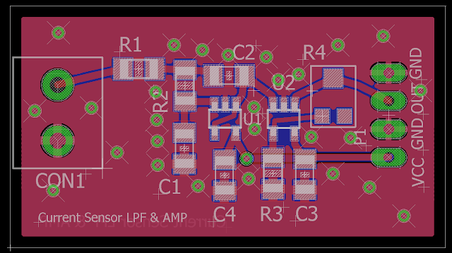
In this three part series we look at how to design a signal conditioning circuit to increase the accuracy and resolution of your ADC measurements. The signal conditioning circuit consists of a double pole active Sallen Key Low Pass Filter and a non-inverting op amp. The filter portion is meant to attenuate high frequency noise from your sensor signal to increase measurement accuracy. The amplifier portion scales the signal up to the full range of the ADC to ensure you are getting max resolution. In part 2 we do the PCB layout of our circuit using Eagle CAD software.


You can access the Eagle files on Github at: https://github.com/ForceTronics/Sallen-Key-Low-Pass-Filter-Design/tree/master


Monday, February 27, 2017

Reduce Noise in Your Sensor Measurements with an Active Low Pass Filter Part 1

In this three part series we look at how to design a signal conditioning circuit to increase the accuracy and resolution of your ADC measurements. The signal conditioning circuit consists of a double pole active Sallen Key Low Pass Filter and a non-inverting op amp. The filter portion is meant to attenuate high frequency noise from your sensor signal to increase measurement accuracy. The amplifier portion scales the signal up to the full range of the ADC to ensure you are getting max resolution.


You can find the online filter calculator used in part one at this link: http://sim.okawa-denshi.jp/en/OPseikiLowkeisan.htmk

You can access the LTspice file on Github at: https://github.com/ForceTronics/Sallen-Key-Low-Pass-Filter-Design/tree/master

Sallen-Key Low Pass Filter Circuit with Amplifier Stage in LTspice