The ForceTronics blog provides tutorials on creating fun and unique electronic projects. The goal of each project will be to create a foundation or jumping off point for amateur, hobbyist, and professional engineers to build on and innovate. Please use the comments section for questions and go to forcetronics.com for information on forcetronics consulting services.
In this video we give an overview of the USB type-C connector standard along with other related USB standards. We then look at an example design that implements a USB type-C connector and converts the USB 2.0 communication to serial or UART communication. You can then use the serial data to communicate, debug, or program your microcontroller for programming environments such as Arduino.
In this two part series we look at how to control a Solenoid using an ESP32 board and the Arduino IoT Cloud. In part one we focus on what a solenoid is and the hardware needed to drive a solenoid open or closed. In part 2 we focus on setting up the Arduino IoT Cloud control.
In this tutorial we look at how to combat switch bounce when using a rotary encoder with a debounce circuit made up of fairly basic components (see below). We use the KY-040 encoder as the test subject in the video. Below is the parts list from the video.
Parts list: BAS16-HE3-18 (Diode), SN74LVC1G17QDCKRQ1 (Schmitt Trigger), standard 0805 resistors (300ohms and 15kohms), and 4.7uF 0805 ceramic capacitor
Code from example ESP32 and KY-040 application in the video
//This sketch demonstrates how to use the KY-040 encoder
//link to KY-040 https://www.epitran.it/ebayDrive/datasheet/25.pdf
//encoder pins
#include <Adafruit_NeoPixel.h>
#define ECLK 26 //encoder CLK pin
#define EDT 25 //encoder DT pin
#define ESW 35 //encoder SW pin
#define LED_PIN 13 //pin for LED comm
#define LED_CNT 1 //LED cnt
#define BRIGHTNESS 125 //LED brightness setting
//First argument is number of LEDs, second is arduino pin
Adafruit_NeoPixel pixels = Adafruit_NeoPixel(LED_CNT,LED_PIN, NEO_GRB + NEO_KHZ800);
const uint32_t off = pixels.Color(0, 0, 0); //RGB value for off
const uint32_t white = pixels.Color(127, 127, 127); //RGB color for white
const uint32_t blue = pixels.Color(30,144,255); //RGB color for blue
const uint32_t red = pixels.Color(255, 0, 0); //RGB color for red
volatile bool buttonFlag = false; //flag that tracks if button was pressed
volatile uint8_t encoderFlag = 0; //flog for tracking encoder turns
bool ledState = false; //tracks whether to turn LED off or on for button presses
//interrupt service routine for an encoder turn CC or CCW
void IRAM_ATTR ISR() { encoderFlag = true; }
//interrupt service routine for an encoder button press
void IRAM_ATTR ISR2() {
buttonFlag = true;
}
void setup() {
pinMode(ECLK,INPUT); //setup encoder pins
pinMode(EDT,INPUT);
pinMode(ESW,INPUT);
attachInterrupt(ECLK, ISR, FALLING); //setup encoder interrupts
attachInterrupt(ESW, ISR2, FALLING);
pixels.begin(); //start RGB LED object
pixels.setBrightness(BRIGHTNESS); //set LED brightness
setLED(off); //set LED off
}
void loop() {
if(encoderFlag) { //encoder knob was turned
if(digitalRead(EDT)) { //encoder turned clockwise
setLED(blue);
}
else { //encoder was turned counter clockwise
setLED(red);
}
encoderFlag = false; //reset flag
}
if(buttonFlag) { //button was pressed
buttonFlag = false; //reset flag
if(ledState) {
setLED(off);
ledState = false;
}
else {
setLED(white);
ledState = true;
}
}
}
//sets LED to a specified RGB color
//input is the RGB value
void setLED(uint32_t color) {
for(int i=0;i<1;i++){
pixels.setPixelColor(i,color); //set LED color
pixels.show(); //send updated state to LED
}
}
In this video we look at how to setup and change the system clock on the SAMD21 family of microcontrollers from Microchip / Atmel. This example code is written in C++ and uses direct register access.
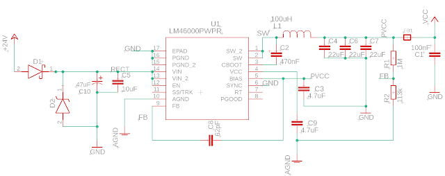
In the video we look at how to design a 24VAC power supply for industrial and HVAC applications. The supply will be flexible enough to handle DC voltage inputs. The power supply will employ a DC to DC buck converter, half wave rectifier, input protection against over voltage, and output noise reduction circuit features. In part 2 we look at the PCB design, the finished product, and capture some test data to see how it is working.
In the video we look at how to design a 24VAC power supply for industrial and HVAC applications. The supply will be flexible enough to handle DC voltage inputs. The power supply will employ a DC to DC buck converter, half wave rectifier, input protection against over voltage, and output noise reduction circuit features
Link to the ferrite bead article mentioned in the video: https://www.analog.com/en/analog-dialogue/articles/ferrite-beads-demystified.html#
Link to TI Webbench Power Designer tool: https://webench.ti.com/power-designer/switching-regulator
In this video we will design an automatic battery cutoff circuit to prevent damaging over discharge of rechargeable batteries. In part 2 we test the design and discuss MOSFET and Voltage Detector specs.
BOM of battery cutoff circuit:
S-1011A70-M6T1U4 Voltage Detector from ABLIC
DMP4015SSS-13 P Chan MOSFET from Diodes Inc
BSS138 N Chan MOSFET from multiple manufacturers
RSX051VYM30FHTR Schottky Diode from ROHM Semi
2x 3.3 nF Ceramic Capacitor
~100 kOhm Resistor
1 to 10 MOhm Resistor (used 4.7M in example circuit)