Tuesday, July 21, 2015

Using a Transistor as a Switch

In this video we cover briefly what a transistor is and discuss how to use them as an electrical switch (DC only). As a demonstration we use an Arduino to switch on and off an NPN transistor and a PNP transistor.


//************************Arduino Code ******************************
//This example code was used on the Forcetronics YouTube Channel to demonstrate how to
//make an inverter or not gate using an NPN and PNP transistor. This code is open for
//anybody to use or modify

const int BJT = 2; //create variable to control the base of NPN and PNP

void setup() {
  pinMode(BJT, OUTPUT);   // set it as digital output
}

void loop() {
  digitalWrite(BJT, LOW);   // set base of NPN and PNP to low
  delay(1000);
  digitalWrite(BJT, HIGH);   // set base of NPN and PNP to high
  delay(1000);
}
Friday, July 10, 2015

Building Your Own AVR / Arduino Internet of Things (IoT) Development Board Part 4

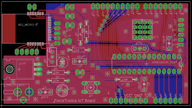
This is part 4 in a 5 part series where we build our own AVR / Arduino Internet of Things (IoT) development board, yay! In this part we will do the PCB layout and discuss how to get our PCB manufactured.


Download Eagle Files


Eagle Parts and Libraries
Libraries Used:
•Atmega 328P --> Library: SparkFun-DigitalIC Device: ATMEGA328P_PDIP
•LM317 --> Library: linear>*317 Device:317T
•Resonator ZTT16.0MHz --> Library: Adafruit Device: CERMOSCILL-THM (CERMOSCILL)
•Ceramic Cap --> Library: rcl > C-EU Device: C-EU050-030X075
•Electrolytic cap --> Library: rcl > CPOL-EU Device: CPOL-EUE2.5-6
•Resistor --> Library: resistor Device: R-EU_0207/10 (R-EU_) Package: 0207/10
•Reset switch --> Library: switch-omron Device: 10-XX
•LED --> Library: led Device: LED5MM (LED)
•Potentiometer --> Library: rcl > R-TRIMM Device: R-TRIMMT93YA
Note: Sparkfun and Adafruit libraries did not come with Eagle, but you can find them on their websites

Parts I made (included in files linked to my blog):
•ForceTronic.lbr --> All header and pin holes and 2.1mm DC Jack
•BLE_Micro_Module.lbr --> BLE Micro

Monday, July 6, 2015

Building Your Own AVR / Arduino Internet of Things (IoT) Development Board Part 3

This is part 3 in a 5 part series where we build our own AVR / Arduino Internet of Things (IoT) development board, yay! In this part we will finalize our design schematic and parts list so we are ready to do PCB layout in part 4.


Final Design Schematic:


Bill of Materials:
  • Atmega 328P MCU (Dip Package)
  • 16MHz resonator
  • BLE Micro from DFRobot or equivalent
  • LM317 Voltage Regulator
  • Resistors (Ohms): 10k, 2x 1k, 2x 300, 1k POTENTIOMETER or 500
  • Capacitors: 4x 100nF (Ceramic) and 1uF (electrolytic)
  • LED 5mm (any color you want)
  • 0.1” male pins
  • 2x 0.1” 2x4 female header (optional)
  • 4x 0.1” pin jumpers
  • DC Power Jack (+ pin is 2.1mm) 
  • 13uH Inductor (optional)
  • Female pin headers: 6 pin, 2x 8 pin, 10 pin
  • 28 pin DIP Socket (optional): part # 4828-3004-CP

Wednesday, June 17, 2015

Building Your Own AVR / Arduino Internet of Things (IoT) Development Board Part 2

This is part 2 in a 5 part series where we build our own AVR / Arduino Internet of Things (IoT) development board, yay! In this part we add the Arduino bootloader to our Atmega 328p as well as build and test a prototype of our design.


BLE Micro Shield Eagle Files 1.0 version (use at your own risk):
https://dl.dropboxusercontent.com/u/26591541/BLE%20Shield.zip


//*******************Arduino Code**********************************************
/*
  This sketch is part of a video tutorial on the ForceTronics YouTube Channel for Building Your AVR/Arduino IoT Development Board 
  which uses a Atmega 328p and a Bluetooth low energy module. 
  The bluetooth module is connected to an Arduino and the Arduino is connected to an LED. 

  This code is in the public domain.
 */

// Pin 13 has a LED connected to it
int led = 13;

// the setup routine runs once when you press reset:
void setup() {
  
  Serial.begin(115200);
  // initialize the digital pin as an output and set it low initially
  pinMode(led, OUTPUT);
  digitalWrite(led, LOW);
}

// the loop routine runs over and over again forever:
void loop() {
  delay(30);
  String t; //create an empty string to store messages from Android
  while(Serial.available()) { //keep reading bytes while they are still more in the buffer
    t += (char)Serial.read(); //read byte, convert to char, and append it to string
  }
  
  if(t.length()) { //if string is not empty do the following
    if(t == "on") { //if the string is equal to "on" then turn LED on
      digitalWrite(led, HIGH); //Set digital pin to high to turn LED on
      Serial.write("LED is on"); //Tell the Android app that the LED was turned on
    }
    else if (t == "off") { 
      digitalWrite(led, LOW);  
      Serial.write("LED is off");
    } // turn the LED off by making the voltage LOW
  }
}

Sunday, June 7, 2015

Intro to Bluetooth Low Energy (BLE) and the BLE Micro

In this video we will take a look at Bluetooth Low Energy or Bluetooth Smart and compare it to classic Bluetooth. From there we will look at how to get started with the BLE Micro module and look at how to communicate with it from an iOS device and another BLE Micro Module.


************************Arduino Code****************************************
/*
  This sketch is part of a video tutorial on the ForceTronics YouTube Channel for using the BLE Micro module which uses Bluetooth low energy. 
  The bluetooth module is connected to an Arduino and the Arduino is connected to an LED. 

  This code is in the public domain.
 */

// Pin 7 has a LED connected to it
int led = 7;

// the setup routine runs once when you press reset:
void setup() {
  
  Serial.begin(115200);
  // initialize the digital pin as an output and set it low initially
  pinMode(led, OUTPUT);
  digitalWrite(led, LOW);
}

// the loop routine runs over and over again forever:
void loop() {
  delay(30);
  String t; //create an empty string to store messages from Android
  while(Serial.available()) { //keep reading bytes while they are still more in the buffer
    t += (char)Serial.read(); //read byte, convert to char, and append it to string
  }
  
  if(t.length()) { //if string is not empty do the following
    if(t == "on") { //if the string is equal to "on" then turn LED on
      digitalWrite(led, HIGH); //Set digital pin to high to turn LED on
      Serial.write("LED is on"); //Tell the Android app that the LED was turned on
    }
    else if (t == "off") { 
      digitalWrite(led, LOW);  
      Serial.write("LED is off");
    } // turn the LED off by making the voltage LOW
  }
}

Tuesday, June 2, 2015

Building Your Own AVR / Arduino Internet of Things (IoT) Development Board Part 1

In this 5 part video series we will build our own AVR / Arduino Internet of Things (IoT) development board. We will go from a design concept to prototyping our design to PCB layout of our design all the way to a tested and finished development board.


Example parts order for this project (please note that this does not include all the parts)


Wednesday, May 20, 2015

Reducing the Power Consumption of the nRF24L01 Transceiver

In this video we take a look at the power needs or power profile of the nRF24L01+ Transceiver. We discuss how much power it draws in each mode and how to reduce or optimize its power consumption for battery powered projects or designs. Finally we pair the nRF24L01 with an Arduino utilizing sleep mode and look at their combined power profile.


************Arduino and nRF24L01 Low Power Example Sketch*************
#include <SPI.h> //Call SPI library so you can communicate with the nRF24L01+
#include <nRF24L01.h> //nRF2401 libarary found at https://github.com/tmrh20/RF24/
#include <RF24.h> //nRF2401 libarary found at https://github.com/tmrh20/RF24/
#include <avr/sleep.h>
#include <avr/wdt.h> 

/*WDT BYTE variables for setting timer value
     WDTO_15MS, WDTO_30MS, WDTO_60MS, WDTO_120MS, WDTO_250MS, WDTO_500MS, WDTO_1S, WDTO_2S, WDTO_4S, WDTO_8S */

const int pinCE = 9; //This pin is used to set the nRF24 to standby (0) or active mode (1)
const int pinCSN = 10; //This pin is used to tell the nRF24 whether the SPI communication is a command or message to send out
RF24 wirelessSPI(pinCE, pinCSN); // Create your nRF24 object or wireless SPI connection
const uint64_t wAddress = 0xB00B1E50D2LL;              // Pipe to write or transmit on
const uint64_t rAddress = 0xB00B1E50B1LL;  //pipe to recive data on

void setup() {
  randomSeed(analogRead(0)); //create unique seed value for random number generation
  wirelessSPI.begin();            //Start the nRF24 module
  wirelessSPI.setRetries(15,10);
  wirelessSPI.openWritingPipe(wAddress);        //open writing or transmit pipe
  wirelessSPI.openReadingPipe(1,rAddress);  //open reading or recieve pipe
  wirelessSPI.stopListening(); //go into transmit mode
}

void loop() {
   byte randNumber = (byte)random(11); //generate random guess between 0 and 10 
    if (!wirelessSPI.write(&randNumber, 1)){  //if the write fails
      // delivery failed      
     }
     
   delay(30); //delay for short time in normal mode
   wirelessSPI.powerDown(); //put nRF24L01 into power down mode
   delayWDT(WDTO_30MS);   // Use WDT sleep delay function, argument is byte variable from WDT Library
   wirelessSPI.powerUp(); //power up the nRF24
}

//This function serves as a power saving delay function. The argument is a Byte type variable that is used to set the delay time
//The function sets up sleep mode in power down state. The function then sets up the WDT timer in interrupt mode and sets it.
//It then puts the Arduino to sleep for the set time. Upon wake up the WDT and sleep mode are shut off
void delayWDT(byte timer) {
  sleep_enable(); //enable the sleep capability
  set_sleep_mode(SLEEP_MODE_PWR_DOWN); //set the type of sleep mode. Default is Idle
  ADCSRA &= ~(1<<ADEN); //Turn off ADC before going to sleep (set ADEN bit to 0)
  WDTCSR |= 0b00011000;    //Set the WDE bit and then clear it when set the prescaler, WDCE bit must be set if changing WDE bit   
  WDTCSR =  0b01000000 | timer; //Or timer prescaler byte value with interrupt selectrion bit set
  wdt_reset(); //Reset the WDT 
  sleep_cpu(); //enter sleep mode. Next code that will be executed is the ISR when interrupt wakes Arduino from sleep
  sleep_disable(); //disable sleep mode
  ADCSRA |= (1<<ADEN); //Turn the ADC back on
}

//This is the interrupt service routine for the WDT. It is called when the WDT times out. 
//This ISR must be in your Arduino sketch or else the WDT will not work correctly
ISR (WDT_vect) 
{
  wdt_disable();
   MCUSR = 0; //Clear WDT flag since it is disabled, this is optional

}  // end of WDT_vect