The ForceTronics blog provides tutorials on creating fun and unique electronic projects. The goal of each project will be to create a foundation or jumping off point for amateur, hobbyist, and professional engineers to build on and innovate. Please use the comments section for questions and go to forcetronics.com for information on forcetronics consulting services.
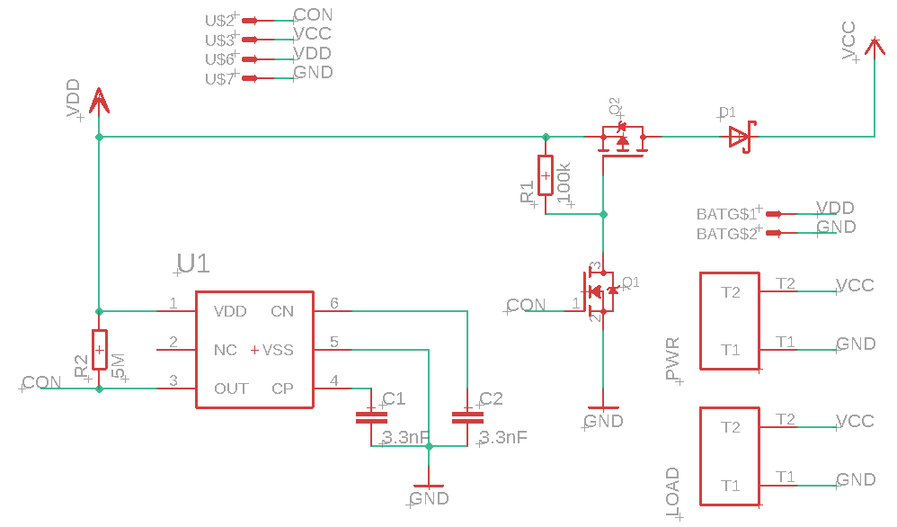
In this video we will design an automatic battery cutoff circuit to prevent damaging over discharge of rechargeable batteries. In part 2 we test the design and discuss MOSFET and Voltage Detector specs.
BOM of battery cutoff circuit:
S-1011A70-M6T1U4 Voltage Detector from ABLIC
DMP4015SSS-13 P Chan MOSFET from Diodes Inc
BSS138 N Chan MOSFET from multiple manufacturers
RSX051VYM30FHTR Schottky Diode from ROHM Semi
2x 3.3 nF Ceramic Capacitor
~100 kOhm Resistor
1 to 10 MOhm Resistor (used 4.7M in example circuit)
In this video we will design an automatic battery cutoff circuit to prevent damaging over discharge of rechargeable batteries. To design our battery cutoff circuit we will use a Voltage Detector or Reset IC.
In part two of this 4 or 5 part series, we look at how the Successive Approximation or SAR ADC architecture works and understand its limitations. Note SAR based ADC architecture is what you typically find in microcontrollers.
In this video series we look at ways or tips to improve ADC measurement accuracy and resolution. In part 1 define what accuracy and resolution is and different types of error that can affect ADC measurements. We also look at the importance of using an accurate ADC reference voltage and why you want to scale the range of the signal you are measuring to the ADC's range.
//***************Arduino code used in video******************************* /*This code demonstrates how to change the ADC voltage reference on an Arduino * This was shown in an ADC tutorial on the ForceTronics YouTube Channel. * This code is free and open for anybody to use at their own risk. */ void setup() { Serial.begin(115200); //setup serial connection while(!Serial); analogReference(AR_EXTERNAL); //sets the ADC reference voltage to external (input is aRef pin) //analogReference(AR_DEFAULT); //set the ADC reference to default which is AVCC (uses power supply voltage or VCC as reference) //analogReference(AR_INTERNAL2V23); //uses 2.23V internal reference in SAMD21 uC analogReadResolution(12); //Set ADC to 12bit resolution, default is 10 burn8Readings(); //make 8 readings but don't use them to ensure good reading after reference change delay(100); for(int i=0;i<500;i++) { //loop through a bunch of ADC readings and print them to serial plotter Serial.println(analogRead(A0)); //Make ADC measurement at A0 } } void loop() { //don't need the loop } //This function makes 8 ADC measurements but does nothing with them //Since after a reference change the ADC can return bad readings at first. This function is used to get rid of the first //8 readings to ensure an accurate one is displayed void burn8Readings() { for(int i=0; i<8; i++) { analogRead(A0); delay(1); } }
Two part tutorial on digital to analog converters (DAC). In part 2 we take a look at the capabilities of the MCP4728 which is a four channel DAC controlled via I2C. See the links below to access the code and get the PCB design from the video at PCBWay.
Link for PCB board at PCBWay: https://www.pcbway.com/project/shareproject/W08904ASW106_DAC_Example_Gerber.html
//**********Arduino Code with MCP4728 examples from video*************** /* * This code was written to demonstrate functions on the MCP4728 4 channel DAC for a video on the ForceTronics YouTube channel * This sketch leverages a library from GitHub made by Hideakitai, link to library: https://github.com/hideakitai/MCP4728 * This code is public domain and free to anyone to use and modify with no restrictions at your own risk */ #include <Wire.h> #include "MCP4728.h" MCP4728 dac; //create object to library //variables for wavform int const sampleCount = 24; //samples to read to have a buffer int signalSamples[sampleCount]; //create array to hold signal or waveform float pi2 = 6.283; //value of pi times 2 const long clkFrequency = 400000; //I2C clock frequency const uint8_t t1 = 3; //pin to setup test 1 fast sinewave const uint8_t t2 = 4; //pin to setup test 2 sync'd sinewaves const uint8_t LDAC = 5; //Output pin on MCU to control LDAC(not) pin on DAC void setup() { //Create sinewave float in; float hBit = 2047.5; for (int i=0;i<sampleCount;i++) { in = pi2*(1/(float)sampleCount)*(float)i; signalSamples[i] = (int)(sin(in)*hBit + hBit); } pinMode(t1,INPUT_PULLUP); //configure test check pins pinMode(t2,INPUT_PULLUP); //configure test check pins pinMode(LDAC,OUTPUT); //configure test check pins digitalWrite(LDAC,HIGH); //turn DAC outputs off Wire.begin(); //start up I2C library Wire.setClock(clkFrequency); //set clock frequency for I2C comm dac.attatch(Wire, 13); //second argument is Arduino pin connected to LDAC(not), we are controlling LDAC manually so just entered pin we are not using dac.readRegisters(); //Used to read current settings from MCP4728 dac.selectVref(MCP4728::VREF::VDD, MCP4728::VREF::VDD, MCP4728::VREF::VDD, MCP4728::VREF::VDD); //setup voltage ref for each DAC channel dac.selectPowerDown(MCP4728::PWR_DOWN::NORMAL, MCP4728::PWR_DOWN::NORMAL, MCP4728::PWR_DOWN::NORMAL, MCP4728::PWR_DOWN::NORMAL); //set power down mode, used for saving power dac.selectGain(MCP4728::GAIN::X1, MCP4728::GAIN::X1, MCP4728::GAIN::X1, MCP4728::GAIN::X1); //set gain on output amp //dac.enable(true); //enables the DAC outputs by controlling LDAC pin, but we are controlling LDAC manually in this example //perform test one if(!digitalRead(t1)) { digitalWrite(LDAC,LOW); //output sinewave as fast as we can for(;;) { //run test for infinitity for(int j=0;j<sampleCount;j++) { dac.analogWrite(MCP4728::DAC_CH::A,signalSamples[j]); } } } else { //perform test 2 for(;;) { //run test for infinitity for(int j=0;j<sampleCount;j++) { int temp = j; digitalWrite(LDAC,HIGH); //turn outputs off // delay(1); dac.analogWrite(MCP4728::DAC_CH::A,signalSamples[temp]); temp += 8; //shift sigal 90 degrees if(temp > 23) temp -= sampleCount; dac.analogWrite(MCP4728::DAC_CH::B,signalSamples[temp]); temp += 8; //shift sigal 90 degrees if(temp > 23) temp -= sampleCount; dac.analogWrite(MCP4728::DAC_CH::C,signalSamples[temp]); temp += 8; //shift sigal 90 degrees if(temp > 23) temp -= sampleCount; dac.analogWrite(MCP4728::DAC_CH::D,signalSamples[temp]); digitalWrite(LDAC,LOW); //turn outputs on all four outputs at same time // delay(1); } } } } void loop() { }
In this video we go over what a digital to analog converter (DAC) is and how it works. We then focus on the MCP4728 4 Channel DAC with some simple examples. In part two we do a deeper dive into the MCP4728.