Wednesday, March 6, 2019

Tutorial on Digital to Analog Converters (DAC) and Example Using the MCP4728 Part 2

Two part tutorial on digital to analog converters (DAC). In part 2 we take a look at the capabilities of the MCP4728 which is a four channel DAC controlled via I2C. See the links below to access the code and get the PCB design from the video at PCBWay.


Link for PCB board at PCBWay: https://www.pcbway.com/project/shareproject/W08904ASW106_DAC_Example_Gerber.html

//**********Arduino Code with MCP4728 examples from video***************
/*
 * This code was written to demonstrate functions on the MCP4728 4 channel DAC for a video on the ForceTronics YouTube channel
 * This sketch leverages a library from GitHub made by Hideakitai, link to library: https://github.com/hideakitai/MCP4728
 * This code is public domain and free to anyone to use and modify with no restrictions at your own risk
 */

#include <Wire.h>
#include "MCP4728.h"

MCP4728 dac; //create object to library
//variables for wavform
int const sampleCount = 24; //samples to read to have a buffer
int signalSamples[sampleCount]; //create array to hold signal or waveform
float pi2 = 6.283; //value of pi times 2
const long clkFrequency = 400000; //I2C clock frequency
const uint8_t t1 = 3; //pin to setup test 1 fast sinewave
const uint8_t t2 = 4; //pin to setup test 2 sync'd sinewaves
const uint8_t LDAC = 5; //Output pin on MCU to control LDAC(not) pin on DAC

void setup() {
 //Create sinewave
 float in;
 float hBit = 2047.5;
 for (int i=0;i<sampleCount;i++)
 {
   in = pi2*(1/(float)sampleCount)*(float)i;
   signalSamples[i] = (int)(sin(in)*hBit + hBit);
 }

 pinMode(t1,INPUT_PULLUP); //configure test check pins
 pinMode(t2,INPUT_PULLUP); //configure test check pins
 pinMode(LDAC,OUTPUT); //configure test check pins
 digitalWrite(LDAC,HIGH); //turn DAC outputs off
 Wire.begin(); //start up I2C library
 Wire.setClock(clkFrequency); //set clock frequency for I2C comm
 dac.attatch(Wire, 13); //second argument is Arduino pin connected to LDAC(not), we are controlling LDAC manually so just entered pin we are not using
 dac.readRegisters(); //Used to read current settings from MCP4728
 dac.selectVref(MCP4728::VREF::VDD, MCP4728::VREF::VDD, MCP4728::VREF::VDD, MCP4728::VREF::VDD); //setup voltage ref for each DAC channel
 dac.selectPowerDown(MCP4728::PWR_DOWN::NORMAL, MCP4728::PWR_DOWN::NORMAL, MCP4728::PWR_DOWN::NORMAL, MCP4728::PWR_DOWN::NORMAL); //set power down mode, used for saving power
 dac.selectGain(MCP4728::GAIN::X1, MCP4728::GAIN::X1, MCP4728::GAIN::X1, MCP4728::GAIN::X1); //set gain on output amp
 //dac.enable(true); //enables the DAC outputs by controlling LDAC pin, but we are controlling LDAC manually in this example

  //perform test one
  if(!digitalRead(t1)) {
    digitalWrite(LDAC,LOW);
    //output sinewave as fast as we can
    for(;;) { //run test for infinitity 
      for(int j=0;j<sampleCount;j++) {
        dac.analogWrite(MCP4728::DAC_CH::A,signalSamples[j]);
      }
    }
  }
  else { //perform test 2 
    for(;;) {  //run test for infinitity 
      for(int j=0;j<sampleCount;j++) {
        int temp = j;
        digitalWrite(LDAC,HIGH); //turn outputs off
       // delay(1);
        dac.analogWrite(MCP4728::DAC_CH::A,signalSamples[temp]);
        temp += 8; //shift sigal 90 degrees
        if(temp > 23) temp -= sampleCount;
        dac.analogWrite(MCP4728::DAC_CH::B,signalSamples[temp]);
        temp += 8; //shift sigal 90 degrees
        if(temp > 23) temp -= sampleCount;
        dac.analogWrite(MCP4728::DAC_CH::C,signalSamples[temp]);
        temp += 8; //shift sigal 90 degrees
        if(temp > 23) temp -= sampleCount;
        dac.analogWrite(MCP4728::DAC_CH::D,signalSamples[temp]);
        digitalWrite(LDAC,LOW); //turn outputs on all four outputs at same time
       // delay(1);
      }
    }
  }
}

void loop() {
}


Saturday, February 16, 2019

Tutorial on Digital to Analog Converters (DAC) and Example Using the MCP4728 Part 1

In this video we go over what a digital to analog converter (DAC) is and how it works. We then focus on the MCP4728 4 Channel DAC with some simple examples. In part two we do a deeper dive into the MCP4728.


Link to Analog Devices detailed tutorial on converters: https://www.analog.com/media/en/training-seminars/design-handbooks/Basic-Linear-Design/Chapter6.pdf
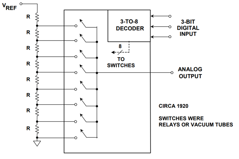
Kelvin Divider or String DAC Architecture

Friday, November 23, 2018

Unboxing Particle's Mesh Network IoT Series (Boron and Xenon)

In this video we unbox Particle's new IoT Mesh Network series (Argon, Boron, Xenon). We take a look both the hardware and the software that allows you to easily create a cloud connected mesh network. Link to product page: https://www.particle.io/mesh


//******************Code from Video*****************************************
// -----------------------------------
// Controlling LEDs over the Internet
// -----------------------------------

// First, let's create our "shorthand" for the pins
// Same as in the Blink an LED example:
// led1 is D0, led2 is D7

int led1 = D0;
int led2 = D7;

// Last time, we only needed to declare pins in the setup function.
// This time, we are also going to register our Particle function

void setup()
{

   // Here's the pin configuration, same as last time
   pinMode(led1, OUTPUT);
   pinMode(led2, OUTPUT);

   // We are also going to declare a Particle.function so that we can turn the LED on and off from the cloud.
   Particle.function("led",ledToggle);
   // This is saying that when we ask the cloud for the function "led", it will employ the function ledToggle() from this app.

   // For good measure, let's also make sure both LEDs are off when we start:
   digitalWrite(led1, LOW);
   digitalWrite(led2, LOW);

}


// Last time, we wanted to continously blink the LED on and off
// Since we're waiting for input through the cloud this time,
// we don't actually need to put anything in the loop

void loop()
{
   // Nothing to do here
}

// We're going to have a super cool function now that gets called when a matching API request is sent
// This is the ledToggle function we registered to the "led" Particle.function earlier.


int ledToggle(String command) {
    /* Particle.functions always take a string as an argument and return an integer.
    Since we can pass a string, it means that we can give the program commands on how the function should be used.
    In this case, telling the function "on" will turn the LED on and telling it "off" will turn the LED off.
    Then, the function returns a value to us to let us know what happened.
    In this case, it will return 1 for the LEDs turning on, 0 for the LEDs turning off,
    and -1 if we received a totally bogus command that didn't do anything to the LEDs.
    */

    if (command=="on") {
        digitalWrite(led1,HIGH);
        digitalWrite(led2,HIGH);
        Particle.publish("LED State", "ON");
        return 1;
    }
    else if (command=="off") {
        digitalWrite(led1,LOW);
        digitalWrite(led2,LOW);
        Particle.publish("LED State", "OFF");
        return 0;
    }
    else {
        return -1;
    }
}

Friday, November 9, 2018

Designing a Thermocouple Temperature Measurement Circuit Part 2

In this series we look at how to design a Thermocouple temperature measurement circuit. In part 2 we look at a real world example of a Thermocouple J Type circuit design and discuss some of the common sources of error and how to avoid them.


Wednesday, October 10, 2018

Designing a Thermocouple Temperature Measurement Circuit Part 1

In this series we look at how to design a Thermocouple temperature measurement circuit. In part 1 we look at Thermocouple theory, pros and cons versus other temperature measurement techniques, and an overview of a measurement hardware circuit as well as calculations done in software.


Wednesday, September 26, 2018

Easy Way to Create a Wireless Sensor Network

In this video we look at an easy way with not very much code to setup a wireless network using the nRF24L01 Transceiver and Arduino.


//***************************Master or Receiver code*****************
/*This code was used for a video tutorial on the ForceTronics YouTube Channel
 * This code is free and open for anybody to use and modify at your own risk
*/

#include <SPI.h> //Call SPI library so you can communicate with the nRF24L01+
#include <nRF24L01.h> //nRF2401 libarary found at https://github.com/tmrh20/RF24/
#include <RF24.h> //nRF2401 libarary found at https://github.com/tmrh20/RF24/

const uint8_t pinCE = 9; //This pin is used to set the nRF24 to standby (0) or active mode (1)
const uint8_t pinCSN = 10; //This pin is used for SPI comm chip select
RF24 wirelessSPI(pinCE, pinCSN); // Declare object from nRF24 library (Create your wireless SPI) 
const uint64_t rAddress = 0xB00B1E50C3LL;  //Create pipe address for the network and notice I spelled boobies because I am mature, the "LL" is for LongLong type
const uint8_t rFChan = 89; //Set channel frequency default (chan 84 is 2.484GHz to 2.489GHz)

//Create a structure to hold fake sensor data and channel data
struct PayLoad {
  uint8_t chan;
  uint8_t sensor;
};

PayLoad payload; //create struct object

void setup() {
  wirelessSPI.begin();  //Start the nRF24 module
  wirelessSPI.setChannel(rFChan); //set communication frequency channel
  wirelessSPI.openReadingPipe(1,rAddress);  //This is receiver or master so we need to be ready to read data from transmitters
  wirelessSPI.startListening();    // Start listening for messages
  Serial.begin(115200);  //serial port to display received data
  Serial.println("Network master is online...");
}

void loop() {
  if(wirelessSPI.available()){ //Check if recieved data
     wirelessSPI.read(&payload, sizeof(payload)); //read packet of data and store it in struct object
     Serial.print("Received data packet from node: ");
     Serial.println(payload.chan); //print node number or channel
     Serial.print("Node sensor value is: ");
     Serial.println(payload.sensor); //print node's sensor value
     Serial.println(); 
  }
}

//***************************Node or Transmitter code*****************
/*This code was used for a video tutorial on the ForceTronics YouTube Channel
 * This code is free and open for anybody to use and modify at your own risk
*/

#include <SPI.h> //Call SPI library so you can communicate with the nRF24L01+
#include <nRF24L01.h> //nRF2401 libarary found at https://github.com/tmrh20/RF24/
#include <RF24.h> //nRF2401 libarary found at https://github.com/tmrh20/RF24/

const uint8_t pinCE = 9; //This pin is used to set the nRF24 to standby (0) or active mode (1)
const uint8_t pinCSN = 10; //This pin is used to tell the nRF24 whether the SPI communication is a command
RF24 wirelessSPI(pinCE, pinCSN); // Declare object from nRF24 library (Create your wireless SPI) 
const uint64_t wAddress = 0xB00B1E50C3LL;  //Create pipe address to send data, the "LL" is for LongLong type
const uint8_t rFChan = 89; //Set channel default (chan 84 is 2.484GHz to 2.489GHz)
const uint8_t rDelay = 7; //this is based on 250us increments, 0 is 250us so 7 is 2 ms
const uint8_t rNum = 5; //number of retries that will be attempted 
const uint8_t chan1 = 2; //D2 pin for node channel check
const uint8_t chan2 = 3; //D3 pin for node channel check
const uint8_t chan3 = 4; //D4 pin for node channel check

//stuct of payload to send fake sensor data and node channel
struct PayLoad {
  uint8_t chan;
  uint8_t sensor;
};

PayLoad payload; //create struct object

void setup() {
  pinMode(chan1,INPUT_PULLUP); //set channel select digital pins to input pullup
  pinMode(chan2,INPUT_PULLUP);
  pinMode(chan3,INPUT_PULLUP);
  wirelessSPI.begin();  //Start the nRF24 module
  wirelessSPI.setChannel(rFChan); 
  wirelessSPI.setRetries(rDelay,rNum); //if a transmit fails to reach receiver (no ack packet) then this sets retry attempts and delay between retries   
  wirelessSPI.openWritingPipe(wAddress); //open writing or transmit pipe
  wirelessSPI.stopListening(); //go into transmit mode
  randomSeed(analogRead(0)); //set random seed for fake sensor data
  setChannel();  //checks current channel setting for transceiver
}

void loop() {
  delay(3000); //send data every 3 seconds
  payload.sensor = random(0,255); //get made up sensor value
  if (!wirelessSPI.write(&payload, sizeof(payload))){  //send data and remember it will retry if it fails
    delay(random(5,20)); //as another back up, delay for a random amount of time and try again
    if (!wirelessSPI.write(&payload, sizeof(payload))){
      //set error flag if it fails again
    }
  }

}

//check for low digital pin to set node address
void setChannel() {
  if(!digitalRead(chan1)) payload.chan = 1;
  else if(!digitalRead(chan2)) payload.chan = 2;
  else if(!digitalRead(chan3)) payload.chan = 3;
  else payload.chan = 0;
}

Sunday, August 19, 2018

Building a UART to USB Memory Stick / Drive Bridge

In this video look at how to create a bridge that takes data from the UART port and writes it to a file on a USB thumb drive (BOMS device). For this project we will use the FT900 microcontroller from FTDI / Bridgetek.


/* Code from the video***********************************************************
 * This is code was used for a Tutorial on the ForceTronics YouTube Channel on writing UART data to a file on a USB thumb drive
 * Most of this code was leveraged from the FTDI / Bridgetek example program called "USBH Example File System" it was written for the FT900
 * family of microcontrollers from FTDI / Bridgetek. This code is free and open for any to use or modify at their own risk
 * */

//all these includes come from the example "USBH Example File System" made by FTDI
#include <stdint.h>
#include <string.h>

#include <ft900.h>
#include <ft900_usb.h>
#include <ft900_usbh_boms.h>
#include <ft900_startup_dfu.h>

// UART support for printf output
#include "tinyprintf.h"

// Support for FATFS 
#include "ff.h"
#include "diskio.h"

/* CONSTANTS ***********************************************************************/

#define EXAMPLE_FILE "FTronics.TXT"
// Change this value in order to change the size of the buffer being used
#define RINGBUFFER_SIZE (4096)

/* GLOBAL VARIABLES ****************************************************************/

// File system handle for fatfs.
FATFS fs;
// Context structure and handle for BOMS device.
USBH_BOMS_context bomsCtx;
USBH_interface_handle hOpenDisk = 0;
USBH_device_handle hRootDev;
unsigned long fPosition = 0; //This variable is used to track the position in the file where the last data was written
volatile unsigned int mTimer = 0; //This variable was used to test how long it took to write data to the file
typedef struct //struct for buffer that stores UART data before it is written to file
{
    uint8_t     data[RINGBUFFER_SIZE];
    uint16_t    wr_idx;
    uint16_t    rd_idx;
} RingBuffer_t;

// Receiver buffer
static RingBuffer_t uart0BufferIn = { {0}, 0, 0 };

/* LOCAL FUNCTIONS / INLINES *******************************************************/
DSTATUS disk_initialize(BYTE pdrv);
DSTATUS disk_status(BYTE pdrv);
DRESULT disk_read (BYTE pdrv, BYTE* buff, DWORD sector, UINT count);
DRESULT disk_write (BYTE pdrv, const BYTE* buff, DWORD sector, UINT count);
DRESULT disk_ioctl (BYTE pdrv, BYTE cmd, void* buff);
DWORD get_fattime(void);

/** @name tfp_putc
 *  @details Machine dependent putc function for tfp_printf (tinyprintf) library.
 *  @param p Parameters (machine dependent)
 *  @param c The character to write
 */
void tfp_putc(void* p, char c)
{
    uart_write((ft900_uart_regs_t*)p, (uint8_t)c);
}

void ISR_timer(void) //this interrupt fires every ten milliseconds to handle USB functions
{
    if (timer_is_interrupted(timer_select_a))
    {
    // Call USB timer handler to action transaction and hub timers.
    USBH_timer();
    mTimer++;
    }
}

/* FatFS Functions ******************/

/** Initialise a drive
 *  @param pdrv Physical Drive number
 *  @return Disk Status */
DSTATUS disk_initialize(BYTE pdrv)
{
DSTATUS stat = 0;
int8_t status;

    status = USBH_BOMS_init(hOpenDisk, 0, &bomsCtx);

    if (status != USBH_BOMS_OK)
    {
    tfp_printf("BOMS device could not be initialised: %d\r\n", status);
stat = STA_NOINIT;
hOpenDisk = 0;
    }

return stat;
}

/** Disk Status
 *  @param pdrv Physical Drive number
 *  @return Disk Status */
DSTATUS disk_status(BYTE pdrv)
{
DSTATUS stat = 0;
    
if (0 == hOpenDisk)
    {
stat |= STA_NOINIT;
    }
        
//TODO: perform a GetSense SCSI command to make sure it's there
    if (USBH_BOMS_status(&bomsCtx) != USBH_BOMS_OK)
    {
        stat |= STA_NODISK;
    }

return stat;
}

/** Read sector(s) from disk
 *  @param pdrv Physical Drive number
 *  @param buff Data buffer to store into
 *  @param sector The logical sector address
 *  @param count The number of sectors to read
 *  @return Disk Status */
DRESULT disk_read (BYTE pdrv, BYTE* buff, DWORD sector, UINT count)
{
DRESULT res = RES_OK;

if (USBH_BOMS_read(&bomsCtx, sector, USBH_BOMS_BLOCK_SIZE * count, buff) != USBH_BOMS_OK)
    {
res = RES_ERROR;
    }

return res;
}

#if _USE_WRITE
/** Write sector(s) to the disk
 *  @param pdrv Physical Drive number
 *  @param buff Data buffer to write to the disk
 *  @param sector The logical sector address
 *  @param count The number of sectors to write
 *  @return Disk Status */
DRESULT disk_write (BYTE pdrv, const BYTE* buff, DWORD sector, UINT count)
{
DRESULT res = RES_OK;

if (USBH_BOMS_write(&bomsCtx, sector, USBH_BOMS_BLOCK_SIZE * count, (uint8_t *)buff) != USBH_BOMS_OK)
{
res = RES_ERROR;
    }

return res;
}
#endif

#if _USE_IOCTL
/** Disk IO Control
 *  @param pdrv Physical Drive Number
 *  @param cmd Control Code
 *  @param buff Buffer to send/receive control data 
 *  @return Disk Status */
DRESULT disk_ioctl (BYTE pdrv, BYTE cmd, void* buff)
{
DRESULT res = RES_OK;

    /* Not Supported */

return res;
}
#endif

#if _FS_READONLY == 0
/** Get the current time
 *  @return The time in the following format:
 *          bit[31:25] = Year from 1980 (0..127),
 *          bit[24:21] = Month (1..12),
 *          bit[20:16] = Day of the Month (1..31),
 *          bit[15:11] = Hour (0..23),
 *          bit[10:5]  = Minute (0..59),
 *          bit[4..0]  = Second / 2 (0..29) */
DWORD get_fattime(void)
{
    return 0; /* Invalid timestamp */
}
#endif

/**
 See how much data is available in the UART0 ring buffer

 @return The number of bytes available
 */
uint16_t uart0Available(void)
{
    int16_t diff = uart0BufferIn.wr_idx - uart0BufferIn.rd_idx;

    if (diff < 0)
    {
        diff += RINGBUFFER_SIZE;
    }

    return (uint16_t)diff;
}

/**
 Receive a number of bytes from UART0

 @return The number of bytes read from UART0
 */
uint16_t uart0Rx(uint8_t *data, uint16_t len)
{
    uint16_t avail = 0;
    uint16_t copied = 0;

    avail = uart0Available();

    /* Copy in as much data as we can ...
       This can be either the maximum size of the buffer being given
       or the maximum number of bytes available in the Serial Port
       buffer */
    while(len-- && avail--)
    {
        *data = uart0BufferIn.data[uart0BufferIn.rd_idx];
        data++;

        /* Increment the pointer and wrap around */
        uart0BufferIn.rd_idx++;
        if (uart0BufferIn.rd_idx == RINGBUFFER_SIZE) uart0BufferIn.rd_idx = 0;

        copied++;
    }

    /* Report back how many bytes have been copied into the buffer...*/
    return copied;
}


/**
 The Interrupt which handles asynchronous transmission and reception
 of data into the ring buffer
 */
void uart0ISR()
{
    static uint8_t c;

    /* Receive interrupt... */
    if (uart_is_interrupted(UART0, uart_interrupt_rx))
    {
        /* Read a byte into the Ring Buffer... */
        uart_read(UART0, &c);

        uart0BufferIn.data[uart0BufferIn.wr_idx] = c;

        /* Increment the pointer and wrap around */
        uart0BufferIn.wr_idx++;
        if (uart0BufferIn.wr_idx == RINGBUFFER_SIZE) uart0BufferIn.wr_idx = 0;

        /* Check to see if we have hit the back of the buffer... */
        if (uart0BufferIn.wr_idx == uart0BufferIn.rd_idx)
        {
            /* Increment the pointer and wrap around */
            uart0BufferIn.rd_idx++;
            if (uart0BufferIn.rd_idx == RINGBUFFER_SIZE) uart0BufferIn.rd_idx = 0;
        }
    }
}

//this function mounts file system that the file is written to
int8_t mountFileSystem(USBH_interface_handle hBOMS)
{
    // Initialise FatFS
    hOpenDisk = hBOMS; //this gets USB "interface" handle
    //Would like to make this a one time action
    if (f_mount(&fs, "", 0) != FR_OK) //mounts file system, needed to open file I am assuming
    {
    tfp_printf("Unable to mount File System\r\n");
    return -1;
    }

    tfp_printf("\r\n\r\n"); delayms(1000);

    return 0;
}

//This function creates the file that we are storing on the USB drive
//If the file already exists it will be deleted and a new one is created
int8_t createFile(USBH_interface_handle hBOMS) {
// Initialise FatFS
    hOpenDisk = hBOMS; //this gets USB "interface" handle
    FRESULT res; //file data type, that is an enumeration with states of the file interactions
    FIL f; //another file data type enum with file conditions
    // Check to see if the example file is there.
    //This code checks to see if file already exists
    res = f_stat(EXAMPLE_FILE, NULL);
    if (FR_OK == res)
    {
        tfp_printf("File " EXAMPLE_FILE " already exists. Deleting\r\n");
        if (FR_OK != f_unlink(EXAMPLE_FILE))
        {
        tfp_printf("Problem deleting " EXAMPLE_FILE "\r\n");
        return 0;
        }
    }

    res = f_open(&f, EXAMPLE_FILE, FA_CREATE_NEW);

    if (FR_OK != res)
    {
    tfp_printf("Problem creating file " EXAMPLE_FILE "\r\n");
    return 0;
    }

    tfp_printf( "Closing " EXAMPLE_FILE "\r\n");
        if (FR_OK != f_close(&f)) //This is where the file is closed after writing
        {
        tfp_printf("Error closing " EXAMPLE_FILE "\r\n");
        }

tfp_printf("\r\n\r\n"); delayms(1000);
return 1;
}

//funciton used to write data to the file. the data pointer is for the data you want to write
//this bCount variable is for how much data
int8_t writeDataToFile(USBH_interface_handle hBOMS, uint8_t* data, uint16_t bCount)
{
    FRESULT res; //file data type, that is an enumeration with states of the file interactions
    FIL f; //another file data type enum with file conditions
    UINT towrite, written;

    // Initialise FatFS
    hOpenDisk = hBOMS; //this gets USB "interface" handle which I am guessing is information on the USB device we are working with

    // Write some data to the USB memory stick, this is where we open file to write to
   // tfp_printf( "Opening " EXAMPLE_FILE " for writing\r\n");
    res = f_open(&f, EXAMPLE_FILE, FA_WRITE | FA_OPEN_EXISTING);

    if (FR_OK != res)
    {
    tfp_printf("Problem opening file " EXAMPLE_FILE "\r\n");
    }

    f_lseek (&f, fPosition); //change writing position of the file???

    towrite = bCount;
    written = 0;
    //this is where we write the data to the file. It seems if you mess up setting up USB stuff this is where we fail
    while(towrite)
    {
        f_write(&f, data, towrite, &written);

        towrite -= written;
        data += written;

        tfp_printf("Wrote %d bytes\r\n", written);
    }

    fPosition = fPosition + written;

    tfp_printf( "Closing " EXAMPLE_FILE "\r\n");
    if (FR_OK != f_close(&f)) //This is where the file is closed after writing
    {
    tfp_printf("Error closing " EXAMPLE_FILE "\r\n");
    }

    return 0;
}

//This funciton will read data from file. It is not used in this example and was left in for debugging purposes
int8_t readFromFile(USBH_interface_handle hBOMS)
{
    FIL f; //another file data type enum with file conditions
    UINT read;
    uint8_t* buffer[512]; //buffer for reading file on USB BOMS

    // Initialise FatFS
    hOpenDisk = hBOMS; //this gets USB "interface" handle which I am guessing is information on the USB device we are working with

    //this is where the / a file is open and read
    tfp_printf( "Opening " EXAMPLE_FILE " for reading\r\n\r\n");
    if (FR_OK != f_open(&f, EXAMPLE_FILE, FA_READ))
    {
    tfp_printf("Error opening " EXAMPLE_FILE " for reading\r\n");
    }

    do
    {
        f_read(&f, buffer, 128, &read);
        uart_writen(UART0, (uint8_t *)buffer, read);
    }
    while(read == 128);


    tfp_printf( "\r\n" "Closing " EXAMPLE_FILE "\r\n");
    f_close(&f);


    tfp_printf("\r\n\r\n");

    return 0;
}

//this function does all the setup work for the connected USB drive
USBH_interface_handle doAllUSBStuff(){
uint8_t status;
USBH_STATE connect;
USBH_interface_handle hInterface;
uint8_t usbClass;
uint8_t usbSubclass;
uint8_t usbProtocol;

//First USB action, initialize. There is no function for this so is it part of the USBH library
//This is part of FT900 USB library, notes from doc:Performs a software reset and initialises the USB hardware
USBH_initialise(NULL);

//Second step: Determine if a hub port has a downstream connection.
//Select a hub and a port to query. For the root hub the handle will be NULL and the port zero
//checks if there are multiple ports, and sets if there is a connection
USBH_get_connect_state(USBH_ROOT_HUB_HANDLE, USBH_ROOT_HUB_PORT, &connect);
if (connect == USBH_STATE_NOTCONNECTED)
{
tfp_printf("\r\nPlease plug in a USB Device\r\n");

// You only enter this loop if there is no USB device detected. basically loops until you plug one in
do //looks like this is only called if the first port call fails
{
//Third step: To be continuously called by the user application. Checks for asynchronous transfer completions
//and root hub events. When a root hub connection is detected then the enumeration routine is called automatically.
//There is no requirement to call USBH_enumerate if USBH_process is called periodically.
status = USBH_process();
USBH_get_connect_state(USBH_ROOT_HUB_HANDLE, USBH_ROOT_HUB_PORT, &connect);
} while (connect == USBH_STATE_NOTCONNECTED);
}
tfp_printf("\r\nUSB Device Detected\r\n");

do{ //this loop continues until USB BOMS device is enumerated
status = USBH_process(); //third step, see description above
//USBH_process combined with get connected state does the enumeration
USBH_get_connect_state(USBH_ROOT_HUB_HANDLE, USBH_ROOT_HUB_PORT, &connect);
} while (connect != USBH_STATE_ENUMERATED);

tfp_printf("USB Device Enumerated\r\n");

// Get the first device (device on root hub)
//Step four: Get device list. Get the first child device of a device. The function will return a handle to a device if there are one
//or more child devices. For devices on the root hub the handle is set to USBH_ROOT_HUB_HANDLE.If there are no interfaces then a NULL is returned.
status = USBH_get_device_list(USBH_ROOT_HUB_HANDLE, &hRootDev);

if (status != USBH_OK)
{
// Report the error code.
tfp_printf("%d\r\n", status);
}
else //this is where hub_scan_for_boms function was orginally called in USB test function
{
    //this is a repeated function call (step 4), why do that? probably just to get status data in this function rather than
    //passing it from previous function
    status = USBH_get_interface_list(hRootDev, &hInterface);

    //step 5: Get interface class, subclass and protocol. Get the class information of an interface.
    //This function basically gets the USB characteristics of the attached device
    if (USBH_interface_get_class_info(hInterface, &usbClass, &usbSubclass, &usbProtocol) == USBH_OK)
       {
    if ((usbClass == USB_CLASS_MASS_STORAGE) && //this if statement is checking all the parameters of the previous function
           (usbSubclass == USB_SUBCLASS_MASS_STORAGE_SCSI) &&
            (usbProtocol == USB_PROTOCOL_MASS_STORAGE_BOMS))
          {
          tfp_printf("BOMS device found at level %d\r\n", 1);
          //at this point we have established the connected USB device and we are moving to the file interactions
          //fs_testing(hInterface,"this better print to a mofo text file");
          mountFileSystem(hInterface);
          }
    else {
    tfp_printf("Problem creating and writing to file");
    }
       }
    else {
        tfp_printf("Problem getting USB information");
     }

}

return hInterface;
}

void setup()
{
    /* Check for a USB device connection and initiate a DFU firmware download or
       upload operation. This will timeout and return control here if no host PC
       program contacts the device's DFU interace. USB device mode is disabled
       before returning.
    */
    STARTUP_DFU();

    /* Enable the UART Device... */
        sys_enable(sys_device_uart0);
        /* Make GPIO48 function as UART0_TXD and GPIO49 function as UART0_RXD... */
        gpio_function(48, pad_uart0_txd); /* UART0 TXD */
        gpio_function(49, pad_uart0_rxd); /* UART0 RXD */
        uart_open(UART0,                    /* Device */
                  1,                        /* Prescaler = 1 */
                  UART_DIVIDER_115200_BAUD,  /* Divider = 1302 */
                  uart_data_bits_8,         /* No. Data Bits */
                  uart_parity_none,         /* Parity */
                  uart_stop_bits_1);        /* No. Stop Bits */

        // Enable tfp_printf() functionality...
        init_printf(UART0, tfp_putc);

        sys_enable(sys_device_timer_wdt);

        interrupt_attach(interrupt_timers, (int8_t)interrupt_timers, ISR_timer);

        // Timer A = 1ms
        timer_prescaler(1000);
        timer_init(timer_select_a, 1000, timer_direction_down, timer_prescaler_select_on, timer_mode_continuous);
        timer_enable_interrupt(timer_select_a);
        timer_start(timer_select_a);

        uart_disable_interrupt(UART0, uart_interrupt_tx);
        // Enable the UART to fire interrupts when receiving data...
        uart_enable_interrupt(UART0, uart_interrupt_rx);
        // Attach the interrupt so it can be called...
        interrupt_attach(interrupt_uart0, (uint8_t) interrupt_uart0, uart0ISR);
        // Enable interrupts to be fired...
        uart_enable_interrupts_globally(UART0);
        interrupt_enable_globally();

        hOpenDisk = doAllUSBStuff();
        createFile(hOpenDisk);

}

int main(int argc, char *argv[])
{
setup(); //run code to setup USB and UART communication
fPosition = 0; //reset the file position

while(1) { //loop forever
mTimer = 0; //reset 10 msec timer variable
if (uart0Available()) {
uint8_t buffer[RINGBUFFER_SIZE] = {0};
uint16_t read_bytes = uart0Rx(buffer, RINGBUFFER_SIZE);
writeDataToFile(hOpenDisk, buffer, read_bytes);
tfp_printf("timer value is %d\r\n", mTimer*10);
}

  }

    interrupt_detach(interrupt_timers);
    interrupt_disable_globally();
    sys_disable(sys_device_timer_wdt);
}