Showing posts with label arduino. Show all posts

Thursday, February 23, 2023

Building a Dynamic ESP32 Wireless Network using the ESP-Now Protocol

In this three part series we will design a dynamic wireless network using ESP32 modules and leveraging EXPRESSIF's ESP-NOW communication protocol.

In part 1 we provide an overview of the ESP-NOW communication protocol and talk about how our dynamic wireless network will work.


In part 2 we look at a simple implementation of ESP-Now that will serve as a foundation for the dynamic network we will design and cover in part 3.


Patreon page link: https://www.patreon.com/forcetronics

ESP-NOW documentation: https://docs.espressif.com/projects/esp-idf/en/latest/esp32/api-reference/network/esp_now.html


**************Part 3 coming soon*******************************


Sunday, December 4, 2022

How to Design a Programming Circuit for the ESP32

In the video we look at how to design a circuit for programming an ESP32 module. We also explain the Strapping Pins on the ESP32 and how they work.


Oscilloscope Capture of EN pin and GPIO0 setting ESP32 in Download Boot Mode


Sunday, November 27, 2022

How to Use a USB Type-C Connector in Your Next Microcontroller Based Project

In this video we give an overview of the USB type-C connector standard along with other related USB standards. We then look at an example design that implements a USB type-C connector and converts the USB 2.0 communication to serial or UART communication. You can then use the serial data to communicate, debug, or program your microcontroller for programming environments such as Arduino.


USB Type C Connector example implementation


USB 2.0 communication converted to UART / Serial


Wednesday, September 14, 2022

How to Control Water Flow with Arduino IoT Cloud and a Solenoid Parts 1 and 2

In this two part series we look at how to control a Solenoid using an ESP32 board and the Arduino IoT Cloud. In part one we focus on what a solenoid is and the hardware needed to drive a solenoid open or closed. In part 2 we focus on setting up the Arduino IoT Cloud control.

\


Link to tutorial on setting up device on Arduino IoT Cloud: https://docs.arduino.cc/arduino-cloud/getting-started/esp-32-cloud


//**************Arduino Code from Tutorial*********************
#include "thingProperties.h"

#define SOLENOID_PIN 21

void setup() {
  pinMode(SOLENOID_PIN,OUTPUT);
  digitalWrite(SOLENOID_PIN,LOW);

  // Defined in thingProperties.h
  initProperties();

  // Connect to Arduino IoT Cloud
  ArduinoCloud.begin(ArduinoIoTPreferredConnection);
  
  /*
     The following function allows you to obtain more information
     related to the state of network and IoT Cloud connection and errors
     the higher number the more granular information you’ll get.
     The default is 0 (only errors).
     Maximum is 4
 */
  setDebugMessageLevel(2);
  ArduinoCloud.printDebugInfo();
}

void loop() {
  ArduinoCloud.update();
  
  if(water_Scheduler.isActive() || solenoidState) {
    digitalWrite(SOLENOID_PIN, HIGH);
  }
  else {
    digitalWrite(SOLENOID_PIN, LOW);
  } 
}


/*
  Since SolenoidState is READ_WRITE variable, onSolenoidStateChange() is
  executed every time a new value is received from IoT Cloud.
*/
void onSolenoidStateChange()  {
  // Add your code here to act upon SolenoidState change
  /*
  if (solenoidState) {
    digitalWrite(SOLENOID_PIN, HIGH);
  }
  else {
    digitalWrite(SOLENOID_PIN, LOW);
  } 
  */
}

/*
  Since WaterScheduler is READ_WRITE variable, onWaterSchedulerChange() is
  executed every time a new value is received from IoT Cloud.
*/
void onWaterSchedulerChange()  {
  // Add your code here to act upon WaterScheduler change
}

Saturday, November 13, 2021

How to Build a Switch Debounce Circuit for a Rotary Encoder


In this tutorial we look at how to combat switch bounce when using a rotary encoder with a debounce circuit made up of fairly basic components (see below). We use the KY-040 encoder as the test subject in the video. Below is the parts list from the video.
Parts list: BAS16-HE3-18 (Diode), SN74LVC1G17QDCKRQ1 (Schmitt Trigger), standard 0805 resistors (300ohms and 15kohms), and 4.7uF 0805 ceramic capacitor

Code from example ESP32 and KY-040 application in the video
//**************************************************************************************************************
//This sketch demonstrates how to use the KY-040 encoder //link to KY-040 https://www.epitran.it/ebayDrive/datasheet/25.pdf //encoder pins #include <Adafruit_NeoPixel.h> #define ECLK 26 //encoder CLK pin #define EDT 25 //encoder DT pin #define ESW 35 //encoder SW pin #define LED_PIN 13 //pin for LED comm #define LED_CNT 1 //LED cnt #define BRIGHTNESS 125 //LED brightness setting //First argument is number of LEDs, second is arduino pin Adafruit_NeoPixel pixels = Adafruit_NeoPixel(LED_CNT,LED_PIN, NEO_GRB + NEO_KHZ800); const uint32_t off = pixels.Color(0, 0, 0); //RGB value for off const uint32_t white = pixels.Color(127, 127, 127); //RGB color for white const uint32_t blue = pixels.Color(30,144,255); //RGB color for blue const uint32_t red = pixels.Color(255, 0, 0); //RGB color for red volatile bool buttonFlag = false; //flag that tracks if button was pressed volatile uint8_t encoderFlag = 0; //flog for tracking encoder turns bool ledState = false; //tracks whether to turn LED off or on for button presses //interrupt service routine for an encoder turn CC or CCW void IRAM_ATTR ISR() { encoderFlag = true; } //interrupt service routine for an encoder button press void IRAM_ATTR ISR2() { buttonFlag = true; } void setup() { pinMode(ECLK,INPUT); //setup encoder pins pinMode(EDT,INPUT); pinMode(ESW,INPUT); attachInterrupt(ECLK, ISR, FALLING); //setup encoder interrupts attachInterrupt(ESW, ISR2, FALLING); pixels.begin(); //start RGB LED object pixels.setBrightness(BRIGHTNESS); //set LED brightness setLED(off); //set LED off } void loop() { if(encoderFlag) { //encoder knob was turned if(digitalRead(EDT)) { //encoder turned clockwise setLED(blue); } else { //encoder was turned counter clockwise setLED(red); } encoderFlag = false; //reset flag } if(buttonFlag) { //button was pressed buttonFlag = false; //reset flag if(ledState) { setLED(off); ledState = false; } else { setLED(white); ledState = true; } } } //sets LED to a specified RGB color //input is the RGB value void setLED(uint32_t color) { for(int i=0;i<1;i++){ pixels.setPixelColor(i,color); //set LED color pixels.show(); //send updated state to LED } }


Friday, May 31, 2019

Ways to Improve ADC Measurement Accuracy and Resolution Part 2

In part two of this 4 or 5 part series, we look at how the Successive Approximation or SAR ADC architecture works and understand its limitations. Note SAR based ADC architecture is what you typically find in microcontrollers.


To access the white paper that was referenced to derive the equation related to RC time constants and sampling time: https://www.silabs.com/documents/public/application-notes/AN119.pdf

Cutout from Silicon Labs App Note on calculating settling time for SAR ADC

Saturday, February 16, 2019

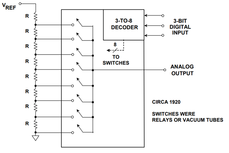
Tutorial on Digital to Analog Converters (DAC) and Example Using the MCP4728 Part 1

In this video we go over what a digital to analog converter (DAC) is and how it works. We then focus on the MCP4728 4 Channel DAC with some simple examples. In part two we do a deeper dive into the MCP4728.


Link to Analog Devices detailed tutorial on converters: https://www.analog.com/media/en/training-seminars/design-handbooks/Basic-Linear-Design/Chapter6.pdf
Kelvin Divider or String DAC Architecture

Wednesday, September 26, 2018

Easy Way to Create a Wireless Sensor Network

In this video we look at an easy way with not very much code to setup a wireless network using the nRF24L01 Transceiver and Arduino.


//***************************Master or Receiver code*****************
/*This code was used for a video tutorial on the ForceTronics YouTube Channel
 * This code is free and open for anybody to use and modify at your own risk
*/

#include <SPI.h> //Call SPI library so you can communicate with the nRF24L01+
#include <nRF24L01.h> //nRF2401 libarary found at https://github.com/tmrh20/RF24/
#include <RF24.h> //nRF2401 libarary found at https://github.com/tmrh20/RF24/

const uint8_t pinCE = 9; //This pin is used to set the nRF24 to standby (0) or active mode (1)
const uint8_t pinCSN = 10; //This pin is used for SPI comm chip select
RF24 wirelessSPI(pinCE, pinCSN); // Declare object from nRF24 library (Create your wireless SPI) 
const uint64_t rAddress = 0xB00B1E50C3LL;  //Create pipe address for the network and notice I spelled boobies because I am mature, the "LL" is for LongLong type
const uint8_t rFChan = 89; //Set channel frequency default (chan 84 is 2.484GHz to 2.489GHz)

//Create a structure to hold fake sensor data and channel data
struct PayLoad {
  uint8_t chan;
  uint8_t sensor;
};

PayLoad payload; //create struct object

void setup() {
  wirelessSPI.begin();  //Start the nRF24 module
  wirelessSPI.setChannel(rFChan); //set communication frequency channel
  wirelessSPI.openReadingPipe(1,rAddress);  //This is receiver or master so we need to be ready to read data from transmitters
  wirelessSPI.startListening();    // Start listening for messages
  Serial.begin(115200);  //serial port to display received data
  Serial.println("Network master is online...");
}

void loop() {
  if(wirelessSPI.available()){ //Check if recieved data
     wirelessSPI.read(&payload, sizeof(payload)); //read packet of data and store it in struct object
     Serial.print("Received data packet from node: ");
     Serial.println(payload.chan); //print node number or channel
     Serial.print("Node sensor value is: ");
     Serial.println(payload.sensor); //print node's sensor value
     Serial.println(); 
  }
}

//***************************Node or Transmitter code*****************
/*This code was used for a video tutorial on the ForceTronics YouTube Channel
 * This code is free and open for anybody to use and modify at your own risk
*/

#include <SPI.h> //Call SPI library so you can communicate with the nRF24L01+
#include <nRF24L01.h> //nRF2401 libarary found at https://github.com/tmrh20/RF24/
#include <RF24.h> //nRF2401 libarary found at https://github.com/tmrh20/RF24/

const uint8_t pinCE = 9; //This pin is used to set the nRF24 to standby (0) or active mode (1)
const uint8_t pinCSN = 10; //This pin is used to tell the nRF24 whether the SPI communication is a command
RF24 wirelessSPI(pinCE, pinCSN); // Declare object from nRF24 library (Create your wireless SPI) 
const uint64_t wAddress = 0xB00B1E50C3LL;  //Create pipe address to send data, the "LL" is for LongLong type
const uint8_t rFChan = 89; //Set channel default (chan 84 is 2.484GHz to 2.489GHz)
const uint8_t rDelay = 7; //this is based on 250us increments, 0 is 250us so 7 is 2 ms
const uint8_t rNum = 5; //number of retries that will be attempted 
const uint8_t chan1 = 2; //D2 pin for node channel check
const uint8_t chan2 = 3; //D3 pin for node channel check
const uint8_t chan3 = 4; //D4 pin for node channel check

//stuct of payload to send fake sensor data and node channel
struct PayLoad {
  uint8_t chan;
  uint8_t sensor;
};

PayLoad payload; //create struct object

void setup() {
  pinMode(chan1,INPUT_PULLUP); //set channel select digital pins to input pullup
  pinMode(chan2,INPUT_PULLUP);
  pinMode(chan3,INPUT_PULLUP);
  wirelessSPI.begin();  //Start the nRF24 module
  wirelessSPI.setChannel(rFChan); 
  wirelessSPI.setRetries(rDelay,rNum); //if a transmit fails to reach receiver (no ack packet) then this sets retry attempts and delay between retries   
  wirelessSPI.openWritingPipe(wAddress); //open writing or transmit pipe
  wirelessSPI.stopListening(); //go into transmit mode
  randomSeed(analogRead(0)); //set random seed for fake sensor data
  setChannel();  //checks current channel setting for transceiver
}

void loop() {
  delay(3000); //send data every 3 seconds
  payload.sensor = random(0,255); //get made up sensor value
  if (!wirelessSPI.write(&payload, sizeof(payload))){  //send data and remember it will retry if it fails
    delay(random(5,20)); //as another back up, delay for a random amount of time and try again
    if (!wirelessSPI.write(&payload, sizeof(payload))){
      //set error flag if it fails again
    }
  }

}

//check for low digital pin to set node address
void setChannel() {
  if(!digitalRead(chan1)) payload.chan = 1;
  else if(!digitalRead(chan2)) payload.chan = 2;
  else if(!digitalRead(chan3)) payload.chan = 3;
  else payload.chan = 0;
}

Sunday, July 15, 2018

Speeding up the ADC on Arduino SAMD21 Boards (Zero, Mkr, etc) Part 2

In this video we look at how to get higher ADC speeds out of Arduino boards that are based off of the SAMD21 microcontroller. In part 2 we discuss memory limitations and we leverage an Adafruit library to do an FFT on the ADC data.


Link to details on PCBWay Maker Contest: ttps://www.pcbway.com/project/PCB_DESIGN_CONTEST.aspx

//*******************Arduino Code from Video*********************************
/*This code is from a tutorial on the ForceTronics YouTube Channel that talks about speeding up the sample rate on Arduino boards 
 * that use the SAMD21 microcontroller like the Arduino Zero or MKR series. This code is free and clear for other to use and modify 
 * at their own risk. 
 */
#include "Adafruit_ZeroFFT.h" //adafruit library for FFT
#include <SPI.h>
#include <SD.h>

const long sRate = 300000; //sample rate of ADC
const int16_t dSize = 1024; //used to set number of samples
const byte chipSelect = 38; //used for SPI chip select pin
const byte gClk = 3; //used to define which generic clock we will use for ADC
const byte intPri = 0; //used to set interrupt priority for ADC
const int cDiv = 1; //divide factor for generic clock
const float period = 3.3334; //period of 300k sample rate
String wFile = "ADC_DATA"; //used as file name to store wind and GPS data
volatile int16_t aDCVal[dSize]; //array to hold ADC samples
volatile int count = 0; //tracks how many samples we have collected
bool done = false; //tracks when done writing data to SD card

void setup() {
  portSetup(); //setup the ports or pin to make ADC measurement
  genericClockSetup(gClk,cDiv); //setup generic clock and routed it to ADC
  aDCSetup(); //this function set up registers for ADC, input argument sets ADC reference
  setUpInterrupt(intPri); //sets up interrupt for ADC and argument assigns priority
  aDCSWTrigger(); //trigger ADC to start free run mode
}

void loop() {
  
  if(count==(dSize-1) and !done) { //if done reading and they have not been written to SD card yet
    removeDCOffset(aDCVal, dSize, 8); //this function removes DC offset if you are measuring an AC signal
    int16_t fTTVal[dSize]; //array to hold FFT samples
    for(int j=0; j<dSize; j++) fTTVal[j] = aDCVal[j]; //copy one array to another array
    ZeroFFT(fTTVal,dSize); //calculate FFT and store into array
    SD.begin(chipSelect); //start SD card library
    File myFile = SD.open((wFile + ".csv"), FILE_WRITE); //open file to write data to CSV file
    if (myFile) {
      float sTime = 0;
      for (int y = 0; y < dSize; y++) { //write each reading to CSV 
        myFile.print(String(FFT_BIN(y, sRate, dSize))+",");
        myFile.print(String((fTTVal[y]))+",");
        myFile.print(sTime,5); //write each reading to SD card as string
        myFile.print(",");
        myFile.println(String(aDCVal[y])+","); //write each reading to SD card as string
        sTime = sTime + period; //update signal period info
      }
    }
    myFile.close(); //close file
    done = true; //we are done 
  }
}

//function for configuring ports or pins, note that this will not use the same pin numbering scheme as Arduino
void portSetup() {
  // Input pin for ADC Arduino A0/PA02
  REG_PORT_DIRCLR1 = PORT_PA02;

  // Enable multiplexing on PA02_AIN0 PA03/ADC_VREFA
  PORT->Group[0].PINCFG[2].bit.PMUXEN = 1;
  PORT->Group[0].PINCFG[3].bit.PMUXEN = 1;
  PORT->Group[0].PMUX[1].reg = PORT_PMUX_PMUXE_B | PORT_PMUX_PMUXO_B;
}

//this function sets up the generic clock that will be used for the ADC unit
//by default it uses the 48M system clock, input arguments set divide factor for generic clock and choose which generic clock
//Note unless you understand how the clock system works use clock 3. clocks 5 and up can brick the microcontroller based on how Arduino configures things
void genericClockSetup(int clk, int dFactor) {
  // Enable the APBC clock for the ADC
  REG_PM_APBCMASK |= PM_APBCMASK_ADC;
  
  //This allows you to setup a div factor for the selected clock certain clocks allow certain division factors: Generic clock generators 3 - 8 8 division factor bits - DIV[7:0]
  GCLK->GENDIV.reg |= GCLK_GENDIV_ID(clk)| GCLK_GENDIV_DIV(dFactor);
  while (GCLK->STATUS.reg & GCLK_STATUS_SYNCBUSY);  

  //configure the generator of the generic clock with 48MHz clock
  GCLK->GENCTRL.reg |= GCLK_GENCTRL_GENEN | GCLK_GENCTRL_SRC_DFLL48M | GCLK_GENCTRL_ID(clk); // GCLK_GENCTRL_DIVSEL don't need this, it makes divide based on power of two
  while (GCLK->STATUS.reg & GCLK_STATUS_SYNCBUSY);
  
  //enable clock, set gen clock number, and ID to where the clock goes (30 is ADC)
  GCLK->CLKCTRL.reg |= GCLK_CLKCTRL_CLKEN | GCLK_CLKCTRL_GEN(clk) | GCLK_CLKCTRL_ID(30);
  while (GCLK->STATUS.bit.SYNCBUSY);
}

/*
ADC_CTRLB_PRESCALER_DIV4_Val    0x0u  
ADC_CTRLB_PRESCALER_DIV8_Val    0x1u   
ADC_CTRLB_PRESCALER_DIV16_Val   0x2u   
ADC_CTRLB_PRESCALER_DIV32_Val   0x3u   
ADC_CTRLB_PRESCALER_DIV64_Val   0x4u   
ADC_CTRLB_PRESCALER_DIV128_Val  0x5u   
ADC_CTRLB_PRESCALER_DIV256_Val  0x6u   
ADC_CTRLB_PRESCALER_DIV512_Val  0x7u   
--> 8 bit ADC measurement takes 5 clock cycles, 10 bit ADC measurement takes 6 clock cycles
--> Using 48MHz system clock with division factor of 1
--> Using ADC division factor of 32
--> Sample rate = 48M / (5 x 32) = 300 KSPS
This function sets up the ADC, including setting resolution and ADC sample rate
*/
void aDCSetup() {
  // Select reference
  REG_ADC_REFCTRL = ADC_REFCTRL_REFSEL_INTVCC1; //set vref for ADC to VCC

  // Average control 1 sample, no right-shift
  REG_ADC_AVGCTRL |= ADC_AVGCTRL_SAMPLENUM_1;

  // Sampling time, no extra sampling half clock-cycles
  REG_ADC_SAMPCTRL = ADC_SAMPCTRL_SAMPLEN(0);
  
  // Input control and input scan
  REG_ADC_INPUTCTRL |= ADC_INPUTCTRL_GAIN_1X | ADC_INPUTCTRL_MUXNEG_GND | ADC_INPUTCTRL_MUXPOS_PIN0;
  // Wait for synchronization
  while (REG_ADC_STATUS & ADC_STATUS_SYNCBUSY);

  ADC->CTRLB.reg |= ADC_CTRLB_RESSEL_8BIT | ADC_CTRLB_PRESCALER_DIV32 | ADC_CTRLB_FREERUN; //This is where you set the divide factor, note that the divide call has no effect until you change Arduino wire.c
  //Wait for synchronization
  while (REG_ADC_STATUS & ADC_STATUS_SYNCBUSY);

  ADC->WINCTRL.reg = ADC_WINCTRL_WINMODE_DISABLE; // Disable window monitor mode
  while(ADC->STATUS.bit.SYNCBUSY);

  ADC->EVCTRL.reg |= ADC_EVCTRL_STARTEI; //start ADC when event occurs
  while (ADC->STATUS.bit.SYNCBUSY);

  ADC->CTRLA.reg |= ADC_CTRLA_ENABLE; //set ADC to run in standby
  while (ADC->STATUS.bit.SYNCBUSY);
}

//This function sets up an ADC interrupt that is triggered 
//when an ADC value is out of range of the window
//input argument is priority of interrupt (0 is highest priority)
void setUpInterrupt(byte priority) {
  
  ADC->INTENSET.reg |= ADC_INTENSET_RESRDY; // enable ADC ready interrupt
  while (ADC->STATUS.bit.SYNCBUSY);

  NVIC_EnableIRQ(ADC_IRQn); // enable ADC interrupts
  NVIC_SetPriority(ADC_IRQn, priority); //set priority of the interrupt
}

//software trigger to start ADC in free run
//in future could use this to set various ADC triggers
void aDCSWTrigger() {
  ADC->SWTRIG.reg |= ADC_SWTRIG_START;
}

//This ISR is called each time ADC makes a reading
void ADC_Handler() {
    if(count<1023) {
      aDCVal[count] = REG_ADC_RESULT;
      count++;
    }
    ADC->INTFLAG.reg = ADC_INTENSET_RESRDY; //Need to reset interrupt
}

//This function takes out DC offset of AC signal, it assumes that the offset brings signal to zero volts
//input arguments: array with measured points and bits of measurement
void removeDCOffset(volatile int16_t aDC[], int aSize, int bits) {
  int aSteps = pow(2,bits)/2; //get number of levels in ADC measurement and cut it in half
  for(int i=0; i<aSize; i++) {
    aDC[i] = aDC[i] - aSteps; //take out offset
  }
}

Saturday, June 30, 2018

Speeding up the ADC on Arduino SAMD21 Boards (Zero, Mkr, etc) P1

In this video we look at how to get higher ADC speeds out of Arduino boards that are based off of the SAMD21 microcontroller.


Windows file paths from video:
  • files that define register data structures: C:\Users\yourname\AppData\Local\Arduino15\packages\arduino\hardware\samd\1.6.18\bootloaders\sofia\Bootloader_D21_Sofia_V2.1\src\ASF\sam0\utils\cmsis\samd21\include\component
  • wire.c file path: C:\Users\yourname\AppData\Local\Arduino15\packages\arduino\hardware\samd\1.6.18\cores\arduino

//*******************Arduino example code from video*************************
/*This code is from a tutorial on the ForceTronics YouTube Channel that talks about speeding up the sample rate on Arduino boards 
 * that use the SAMD21 microcontroller like the Arduino Zero or MKR series. This code is free and clear for other to use and modify 
 * at their own risk. 
 */
#include <SPI.h>
#include <SD.h>

const int16_t dSize = 1024; //used to set number of samples
const byte chipSelect = 38; //used for SPI chip select pin
const byte gClk = 3; //used to define which generic clock we will use for ADC
const byte intPri = 0; //used to set interrupt priority for ADC
const int cDiv = 1; //divide factor for generic clock
const float period = 3.3334; //period of 300k sample rate
String wFile = "ADC_DATA"; //used as file name to store wind and GPS data
volatile int aDCVal[dSize]; //array to hold ADC samples
volatile int count = 0; //tracks how many samples we have collected
bool done = false; //tracks when done writing data to SD card

void setup() {
  portSetup(); //setup the ports or pin to make ADC measurement
  genericClockSetup(gClk,cDiv); //setup generic clock and routed it to ADC
  aDCSetup(); //this function set up registers for ADC, input argument sets ADC reference
  setUpInterrupt(intPri); //sets up interrupt for ADC and argument assigns priority
  aDCSWTrigger(); //trigger ADC to start free run mode
}

void loop() {
  
  if(count==(dSize-1) and !done) { //if done reading and they have not been written to SD card yet
    removeDCOffset(aDCVal, dSize, 8); //this function removes DC offset if you are measuring an AC signal
    SD.begin(chipSelect); //start SD card library
    File myFile = SD.open((wFile + ".csv"), FILE_WRITE); //open file to write data to CSV file
    if (myFile) {
      float sTime = 0;
      for (int y = 0; y < dSize; y++) {
        myFile.print(sTime,5); //write each reading to SD card as string
        myFile.print(",");
        myFile.println(String(aDCVal[y])+","); //write each reading to SD card as string
        sTime = sTime + period; //update signal period info
      }
    }
    myFile.close(); //close file
    done = true; //we are done 
  }
}

//function for configuring ports or pins, note that this will not use the same pin numbering scheme as Arduino
void portSetup() {
  // Input pin for ADC Arduino A0/PA02
  REG_PORT_DIRCLR1 = PORT_PA02;

  // Enable multiplexing on PA02_AIN0 PA03/ADC_VREFA
  PORT->Group[0].PINCFG[2].bit.PMUXEN = 1;
  PORT->Group[0].PINCFG[3].bit.PMUXEN = 1;
  PORT->Group[0].PMUX[1].reg = PORT_PMUX_PMUXE_B | PORT_PMUX_PMUXO_B;
}

//this function sets up the generic clock that will be used for the ADC unit
//by default it uses the 48M system clock, input arguments set divide factor for generic clock and choose which generic clock
//Note unless you understand how the clock system works use clock 3. clocks 5 and up can brick the microcontroller based on how Arduino configures things
void genericClockSetup(int clk, int dFactor) {
  // Enable the APBC clock for the ADC
  REG_PM_APBCMASK |= PM_APBCMASK_ADC;
  
  //This allows you to setup a div factor for the selected clock certain clocks allow certain division factors: Generic clock generators 3 - 8 8 division factor bits - DIV[7:0]
  GCLK->GENDIV.reg |= GCLK_GENDIV_ID(clk)| GCLK_GENDIV_DIV(dFactor);
  while (GCLK->STATUS.reg & GCLK_STATUS_SYNCBUSY);  

  //configure the generator of the generic clock with 48MHz clock
  GCLK->GENCTRL.reg |= GCLK_GENCTRL_GENEN | GCLK_GENCTRL_SRC_DFLL48M | GCLK_GENCTRL_ID(clk); // GCLK_GENCTRL_DIVSEL don't need this, it makes divide based on power of two
  while (GCLK->STATUS.reg & GCLK_STATUS_SYNCBUSY);
  
  //enable clock, set gen clock number, and ID to where the clock goes (30 is ADC)
  GCLK->CLKCTRL.reg |= GCLK_CLKCTRL_CLKEN | GCLK_CLKCTRL_GEN(clk) | GCLK_CLKCTRL_ID(30);
  while (GCLK->STATUS.bit.SYNCBUSY);
}

/*
ADC_CTRLB_PRESCALER_DIV4_Val    0x0u  
ADC_CTRLB_PRESCALER_DIV8_Val    0x1u   
ADC_CTRLB_PRESCALER_DIV16_Val   0x2u   
ADC_CTRLB_PRESCALER_DIV32_Val   0x3u   
ADC_CTRLB_PRESCALER_DIV64_Val   0x4u   
ADC_CTRLB_PRESCALER_DIV128_Val  0x5u   
ADC_CTRLB_PRESCALER_DIV256_Val  0x6u   
ADC_CTRLB_PRESCALER_DIV512_Val  0x7u   
--> 8 bit ADC measurement takes 5 clock cycles, 10 bit ADC measurement takes 6 clock cycles
--> Using 48MHz system clock with division factor of 1
--> Using ADC division factor of 32
--> Sample rate = 48M / (5 x 32) = 300 KSPS
This function sets up the ADC, including setting resolution and ADC sample rate
*/
void aDCSetup() {
  // Select reference
  REG_ADC_REFCTRL = ADC_REFCTRL_REFSEL_INTVCC1; //set vref for ADC to VCC

  // Average control 1 sample, no right-shift
  REG_ADC_AVGCTRL |= ADC_AVGCTRL_SAMPLENUM_1;

  // Sampling time, no extra sampling half clock-cycles
  REG_ADC_SAMPCTRL = ADC_SAMPCTRL_SAMPLEN(0);
  
  // Input control and input scan
  REG_ADC_INPUTCTRL |= ADC_INPUTCTRL_GAIN_1X | ADC_INPUTCTRL_MUXNEG_GND | ADC_INPUTCTRL_MUXPOS_PIN0;
  // Wait for synchronization
  while (REG_ADC_STATUS & ADC_STATUS_SYNCBUSY);

  ADC->CTRLB.reg |= ADC_CTRLB_RESSEL_8BIT | ADC_CTRLB_PRESCALER_DIV32 | ADC_CTRLB_FREERUN; //This is where you set the divide factor, note that the divide call has no effect until you change Arduino wire.c
  //Wait for synchronization
  while (REG_ADC_STATUS & ADC_STATUS_SYNCBUSY);

  ADC->WINCTRL.reg = ADC_WINCTRL_WINMODE_DISABLE; // Disable window monitor mode
  while(ADC->STATUS.bit.SYNCBUSY);

  ADC->EVCTRL.reg |= ADC_EVCTRL_STARTEI; //start ADC when event occurs
  while (ADC->STATUS.bit.SYNCBUSY);

  ADC->CTRLA.reg |= ADC_CTRLA_ENABLE; //set ADC to run in standby
  while (ADC->STATUS.bit.SYNCBUSY);
}

//This function sets up an ADC interrupt that is triggered 
//when an ADC value is out of range of the window
//input argument is priority of interrupt (0 is highest priority)
void setUpInterrupt(byte priority) {
  
  ADC->INTENSET.reg |= ADC_INTENSET_RESRDY; // enable ADC ready interrupt
  while (ADC->STATUS.bit.SYNCBUSY);

  NVIC_EnableIRQ(ADC_IRQn); // enable ADC interrupts
  NVIC_SetPriority(ADC_IRQn, priority); //set priority of the interrupt
}

//software trigger to start ADC in free run
//in future could use this to set various ADC triggers
void aDCSWTrigger() {
  ADC->SWTRIG.reg |= ADC_SWTRIG_START;
}

//This ISR is called each time ADC makes a reading
void ADC_Handler() {
    if(count<1023) {
      aDCVal[count] = REG_ADC_RESULT;
      count++;
    }
    ADC->INTFLAG.reg = ADC_INTENSET_RESRDY; //Need to reset interrupt
}

//This function takes out DC offset of AC signal, it assumes that the offset brings signal to zero volts
//input arguments: array with measured points and bits of measurement
void removeDCOffset(volatile int aDC[], int aSize, int bits) {
  int aSteps = pow(2,bits)/2; //get number of levels in ADC measurement and cut it in half
  for(int i=0; i<aSize; i++) {
    aDC[i] = aDC[i] - aSteps; //take out offset
  }
}

Wednesday, May 23, 2018

Building an RGB LED Display Part 1

In video series we build a scalable RGB LED Display or matrix and control it with Arduino. In part 1 we take a close look at the magic of the WS2812B RGB IC and Arduino options for controlling a large display of them.


//***************Arduino Code from Video*************************************
/* This Arduino sketch was made for a tutorial entitled "Building a Fun and Scalable RGB LED Display Part 1" for the ForceTronics YouTube Channel
 *  This sketch was leveraged from an example with the Adafruit NeoPixel library.This sketch was used to compare performance of an Arduino UNO versus 
 *  the Altrium Sno FPGA based Arduino for controlling the ADafruit NeoMatrix. This sketch randomly changes each pixel's brightness and color in a timed
 *  loop.
 *  This code is free for others to use and modify at their own risk
 */

#include <Adafruit_NeoPixel.h> //uncomment this library when using an AVR based Arduino
//#include <XLR8NeoPixel.h> //uncomment this library when using the SNO

// Defines single pin to control NeoMatrix from Arduino
#define PIN            6

//defines number of pixels in the NeoMatrix that was used
#define NUMPIXELS      64

// When we setup the NeoPixel library, we tell it how many pixels, and which pin to use
//We can also set the comm speed and settings related to the how the NeoMatrix is configured
//For more information on how to use arguments for this function go to: https://learn.adafruit.com/adafruit-neopixel-uberguide/neomatrix-library
Adafruit_NeoPixel pixels = Adafruit_NeoPixel(NUMPIXELS, PIN, NEO_GRB + NEO_KHZ800); //decomment this function if you are using an AVR based Arduino
//XLR8NeoPixel pixels = XLR8NeoPixel(NUMPIXELS, PIN, NEO_GRB + NEO_KHZ800); //uncomment this function if you are using the SNO FPGA Arduino

int delayval = 10; // delay for 10 msec

void setup() {
  pixels.begin(); // This initializes the NeoPixel or XLR8NeoPixel library.
}

void loop() {

  // For a set of NeoPixels the first NeoPixel is 0, second is 1, all the way up to the count of pixels minus one.
  //This loops through all the pixels (1 to 64) and then starts back at 1
  for(int i=0;i<NUMPIXELS;i++){
    //This function sets the brightness of a pixel. Brightness can be 0 to 255. Using random() to generate psuedo random value between 0 and 255
    pixels.setBrightness(random(0,255));
    //This function sets the color scheme of an RGB LED, so values are red 0 to 255, green 0 to 255, blue 0 to 255.
    //'i' is the pixel number that is being set and the other arguments are the RGB values which are set using psuedo random values between 0 and 255
    pixels.setPixelColor(i, pixels.Color(random(0,255),random(0,255),random(0,255))); // Moderately bright green color.
    //This function updates the pixels
    pixels.show(); // This sends the updated pixel color to the hardware.
    delay(delayval); // Delay for a period of time (in milliseconds).
  }
}

Sunday, February 11, 2018

Converting an Arduino PWM Output to a DAC Output

In this video we look at how to convert a PWM output or signal to a analog or DAC signal.


To access the low pass filter tutorial mentioned in the video got to: https://youtu.be/gW5oF8vcYb8


//*************Arduino code from video***************************
/*This code was made for a vidoe tutorial on the ForceTronics YouTube Channel called
 * Converting an Arduino PWM Output to a DAC Output. This code is free to use and 
 * modify at your own risk
 */

uint8_t pVal = 127; //PWM value 
const float pi2 = 6.28; //Pie times 2, for building sinewave
const int samples = 100; //number of samples for Sinewave. This value also affects frequency
int WavSamples[samples]; //Array for storing sine wave points
int count = 0; //tracks where we are in sine wave array

void setup() {
// Serial.begin(115200); //for debugging
  pinMode(10, OUTPUT); //pin used for analog voltage value
  pinMode(4,OUTPUT); //pin used to fake PWM for sinewave
  setPwmFrequency(10,1); //function for setting PWM frequency
  analogWrite(10,127); //set duty cycle for PWM

  float in, out; //used for building sine wave
  
  for (int i=0;i<samples;i++) //loop to build sinewave
  {
    in = pi2*(1/(float)samples)*(float)i; //calculate value for sine function
    WavSamples[i] = (int)(sin(in)*127.5 + 127.5); //get sinewave value and store in array
   // Serial.println(WavSamples[i]); //for debugging
  }
}

void loop() {
  if(count > samples) count = 0; //reset the count once we are through array
  bitBangPWM(WavSamples[count],4); //function for turning sinewave into "fake" PWM signal
  count++; //increment position in array
}

//Function to bit bang a PWM signal (we are using it for the sinewave)
//input are PWM high value for one cycle and digital pin for Arduino
//period variable determines frequency along with number of signal samples
//For this example a period of 1000 (which is 1 millisecond) times 100 samples is 100 milli second period so 10Hz
void bitBangPWM(unsigned long on, int pin) {
  int period = 1000; //period in micro seconds
  on = map(on, 0, 255, 0, period); //map function that converts from 8 bits to range of period in micro sec
 // Serial.println(on); //debug check
  unsigned long start = micros(); //get current value of micro second timer as start time
  digitalWrite(pin,HIGH); //set digital pin to high
  while((start+on) > micros()); //wait for a time based on PWM duty cycle
  start = micros(); 
  digitalWrite(pin,LOW); //set digital pin to low
  while((start+(period - on)) > micros()); //wait for a time based on PWM duty cycle
}

/**
 * https://www.arduino.cc/en/Tutorial/SecretsOfArduinoPWM
 * Divides a given PWM pin frequency by a divisor.
 * 
 * The resulting frequency is equal to the base frequency divided by
 * the given divisor:
 *   - Base frequencies:
 *      o The base frequency for pins 3, 9, 10, and 11 is 31250 Hz.
 *      o The base frequency for pins 5 and 6 is 62500 Hz.
 *   - Divisors:
 *      o The divisors available on pins 5, 6, 9 and 10 are: 1, 8, 64,
 *        256, and 1024.
 *      o The divisors available on pins 3 and 11 are: 1, 8, 32, 64,
 *        128, 256, and 1024.
 * 
 * PWM frequencies are tied together in pairs of pins. If one in a
 * pair is changed, the other is also changed to match:
 *   - Pins 5 and 6 are paired on timer0
 *   - Pins 9 and 10 are paired on timer1
 *   - Pins 3 and 11 are paired on timer2
 * 
 * Note that this function will have side effects on anything else
 * that uses timers:
 *   - Changes on pins 3, 5, 6, or 11 may cause the delay() and
 *     millis() functions to stop working. Other timing-related
 *     functions may also be affected.
 *   - Changes on pins 9 or 10 will cause the Servo library to function
 *     incorrectly.
 * 
 * Thanks to macegr of the Arduino forums for his documentation of the
 * PWM frequency divisors. His post can be viewed at:
 *   http://forum.arduino.cc/index.php?topic=16612#msg121031
 */
void setPwmFrequency(int pin, int divisor) {
  byte mode;
  if(pin == 5 || pin == 6 || pin == 9 || pin == 10) {
    switch(divisor) {
      case 1: mode = 0x01; break;
      case 8: mode = 0x02; break;
      case 64: mode = 0x03; break;
      case 256: mode = 0x04; break;
      case 1024: mode = 0x05; break;
      default: return;
    }
    if(pin == 5 || pin == 6) {
      TCCR0B = TCCR0B & 0b11111000 | mode;
    } else {
      TCCR1B = TCCR1B & 0b11111000 | mode;
    }
  } else if(pin == 3 || pin == 11) {
    switch(divisor) {
      case 1: mode = 0x01; break;
      case 8: mode = 0x02; break;
      case 32: mode = 0x03; break;
      case 64: mode = 0x04; break;
      case 128: mode = 0x05; break;
      case 256: mode = 0x06; break;
      case 1024: mode = 0x07; break;
      default: return;
    }
    TCCR2B = TCCR2B & 0b11111000 | mode;
  }
}

Wednesday, January 31, 2018

Designing a Driver Circuit for a Bipolar Stepper Motor Part 2

In this video we design a low cost driver circuit for a four wire bipolar stepper motor using two H bridges.


Link to Eagle files on GitHub: https://github.com/ForceTronics/Bipolar_Stepper_Driver_Circuit/tree/master


Wednesday, December 27, 2017

Designing a Driver Circuit for a Bipolar Stepper Motor Part 1

In this video we design a low cost driver circuit for a four wire bipolar stepper motor using two H bridges.


//********************Arduino code from video***********************
#include <Stepper.h>

const int numberOfSteps = 100;  //number of steps you want your stepper motor to take

// initialize the stepper library on pins 8 through 11:
Stepper myStepper(numberOfSteps, 8, 9, 10, 11);

void setup() {
  // set the speed at 60 rpm:
  myStepper.setSpeed(60);
}

void loop() {
  myStepper.step(numberOfSteps);
  delay(1000);
}

Sunday, November 5, 2017

How to Build a Simple DC Electronic Load with Arduino Part 2

In this video we look at how to make a simple DC electronic load with Arduino and some simple components. In part two 2 we add some flexible measurement capabilities.


//***************************Arduino Code*************************************************
#include <Average.h> /* * This code was used for a tutorial on how to build a simple eload with Arduino * The Tutorial can be found on the ForceTronics YouTube Channel * This code is public domain and free for anybody to use at their own risk */ //Uncomment AVGMEAS to print out avg measurement data and uncomment FASTMEAS to print fast voltage or current measur #define AVGMEAS //#define FASTMEAS //uncomment to print fast current measurements, leave commented to print fast voltage measurements //#define FASTAMP //The following variables set the eload sequence const int sValues[] = {20,50,280}; //set the DAC value for each step const unsigned long sTime[] = {350,50,15}; //set the dwell time for each step const int sNum = 3; //number of steps in the sequence, this number should match the number or items in the arrays long repeat = -1; //set the number of times the sequence repeats, -1 means infinite //The following variables control the measurement rates int measInterval = 5; //in milli seconds, fast measurement rate. This should be less than or equal to measAvgInt int measAvgInt = 1000; //this is done in milliseconds and should be a multiple of the meas interval int aCount = 0; //tracks where we are in the sequence unsigned long sStart; //trcks when a sequence step starts its timer unsigned long mStart; //tracks when a new measurement interval starts unsigned long aHours = 0; //holds amp hour value const unsigned long m2Hours = 360000; //constant value for converting mil sec to hours const float lRes = 5.08; //exact value of eload resistor --> 5.08 const float rMult = 1.51; //multiplier for resistor divider network: R1 = 5.08k and R2 = 9.98k ratio is 9.98 / (9.98 + 5.08) = .663 --> 1.51 const byte aDCVolt = A2; //ADC channel for measuring input voltage const byte aDCCurrent = A4; //ADC channel for measuring voltage across resistor Average<float> voltMeas((measAvgInt/measInterval)); //create average obect to handle voltage measurement data Average<float> currMeas((measAvgInt/measInterval)); //create average object to handle current measurement data void setup() { pinMode(A0, OUTPUT); //A0 DAC pin to output analogWriteResolution(10); //default DAC resolution is 8 bit, swith it to 10 bit (max) analogReadResolution(12); //default ADC resolution is 10 bit, change to 12 bit Serial.begin(57600); analogWrite(A0, sValues[aCount]); //Set DAC value for first step sStart = mStart = millis(); //start timer for seq and measure interval } void loop() { while(repeat > 0 || repeat < 0) { //loop controls how often sequence repeats //timer for changing sequence step if(timer(sTime[aCount],sStart)) { aCount++; //go to next sequence step if(aCount >= sNum) aCount = 0; //if at end go back to beginning analogWrite(A0, sValues[aCount]); //Set DAC value for step sStart = millis(); //reset timer } if(timer(measInterval,mStart)) { voltMeas.push(inputVolt(aDC2Volt(analogRead(aDCVolt)))); //push value into average array currMeas.push(inputCurrent(aDC2Volt(analogRead(aDCCurrent)))); //push value into average array //print input voltage value and current values #ifdef FASTMEAS #ifdef FASTAMP Serial.println(currMeas.get((currMeas.getCount() - 1))*1000); //serial print out of fast current measurements #else Serial.println(voltMeas.get((voltMeas.getCount() - 1))); //serial print out of fast voltage measurements #endif #endif mStart = millis(); //reset timer } //print out average, max / min, and amp hour measurements if(voltMeas.getCount() == (measAvgInt/measInterval)) { #ifdef AVGMEAS Serial.print("Average voltage: "); Serial.print(voltMeas.mean()); Serial.println(" V"); //get and print average voltage value float mA = currMeas.mean()*1000; //get average current value in mA Serial.print("Average current: "); Serial.print(mA); Serial.println(" mA"); //print current value Serial.print("Max voltage: "); Serial.print(voltMeas.maximum()); Serial.println(" V"); //print max and min voltage Serial.print("Min voltage: "); Serial.print(voltMeas.minimum()); Serial.println(" V"); Serial.print("Max current: "); Serial.print(currMeas.maximum()*1000); Serial.println(" mA"); //print max and min current Serial.print("Min current: "); Serial.print(currMeas.minimum()*1000); Serial.println(" mA"); float aH = ampHoursCal(measAvgInt,mA); //calculate how much amp hours of current was consumed since start if(aH < 1000) { Serial.print("Amp hours of power source: "); Serial.print(aH); Serial.println(" uAh"); } //print current in uA else { Serial.print("Amp hours of power source: "); Serial.print(aH/1000); Serial.println(" mAh"); } //print current in mA #endif voltMeas.clear(); //clear voltage measurement array currMeas.clear(); //clear current measurement array } if(repeat > 0) repeat--; //increment repeat if not infinite loop } } //timer function that runs in mill second steps. //Inputs are timer interval and timer start time bool timer(unsigned long tInterval, unsigned long tStart) { unsigned long now = millis(); //get timer value if ((now - tStart) > tInterval ) return true; //check if interval is up return false; //interval is not up } //converts raw ADC reading to voltage value based on 3.3V reference //input is 12 bit ADC value float aDC2Volt(int aDC) { return (((float)aDC/4095)*3.3); } //function converts voltage value to input voltage value based off resistor voltage divider constant //input is measured voltage float inputVolt(float aVolt) { return (rMult*aVolt); } //converts voltage measurement at load resistor to current measurement based on load resistor value //Input is measured voltage float inputCurrent(float rVolt) { return (rVolt/lRes); } //This functions calculates amp hours //amp hour = amp hour value + (amps * (mil sec / 360k) //input: measInt is measurement interval in milli sec and aVal is the measured current value in mA float ampHoursCal(int measInt, float aVal) { aHours = aHours + (aVal * ((double)measInt/m2Hours)*1000); //this converts currect measurement to mA return aHours; }


Wednesday, October 11, 2017

How to Build a Simple DC Electronic Load with Arduino Part 1

In this video we look at how to make a simple DC electronic load with Arduino and some simple components.


//****************Arduino code from video************
/*
 * This code was used for a tutorial on how to build a simple eload with Arduino
 * The Tutorial can be found on the ForceTronics YouTube Channel
 * This code is public domain and free for anybody to use at their own risk
 */
void setup() {
  pinMode(A0, OUTPUT); //A0 DAC pin to output
  analogWriteResolution(10); //default DAC resolution is 8 bit, swith it to 10 bit (max)
}

void loop() {
  //create pulsed current profile
  analogWrite(A0, 16); //Set DAC to approximately 10mV --> current 10mV / 5ohm = 2 mA
  delay(500);
  analogWrite(A0,310); //Set DAC to 1V --> current 1V / 5ohm = 200 mA
  delay(50);

}

Thursday, August 10, 2017

Getting Started with Arduino and the ThingSpeak Cloud

In this video we look at how to use Arduino with the ThingSpeak IoT, cloud, and analytics platform. In the video we look at two use cases of ThingSpeak. For the first use case we log wireless sensor data to the cloud and perform post processing on the data using MATLAB. In the second use case we monitor a room with a wireless motion detector setup and have ThingSpeak send out a Tweet if any movement is detected in the room.


//*****************Arduino code from video**********************************
/*
This sketch was created for a video tutorial on the ForceTronics YouTube that shows how to use Arduino with the ThingSpeak cloud
This code is public domain and free for anybody to use or modify at their own risk

Note this code was leveraged from:
 Arduino --> ThingSpeak Channel via MKR1000 Wi-Fi
 Created: May 7, 2016 by Hans Scharler (http://www.nothans.com)
*/
   
#include <SPI.h>
#include <WiFi101.h> //This sketch should work with any Arduino or shield that can use the WiFi101 library

char ssid[] = "YourNetwork"; //  your network SSID (name)
char pass[] = "YourPassword"; // your network password

int status = WL_IDLE_STATUS;

// Initialize the Wifi clients
WiFiClient tClient; //this one is used to post temperature data
WiFiClient mClient; //this one is used to post motion detection data

// ThingSpeak Settings
char server[] = "api.thingspeak.com";
String writeAPIKey = "YourWriteKey";

//Timing variables for tracking temperature posting
unsigned long tempLastConnectionTime = 0; // track the last connection time
const unsigned long tempPostingInterval = 295000L; // post temp ADC value just under every 5 min

//Timing and logic variables for tracking temperature posting
unsigned long mLastConnectionTime = 0; // track the last connection time
const unsigned long mPostingInterval = 30000L; //checks to see if motion was detected every 30 sec
bool mReset = true; //tracks if motion detection has been reset

void setup() {
  pinMode(2,INPUT); //digital pin used to read output of motion detector
  pinMode(6,OUTPUT); //LED pin used to know when data is sent to cloud
  
  // attempt to connect to Wifi network
  while ( status != WL_CONNECTED) {
    // Connect to WPA/WPA2 Wi-Fi network
    status = WiFi.begin(ssid, pass);
    // wait 10 seconds for connection
    delay(10000);
  }
}

void loop() {
  //timer to know when it is time to post temp data to cloud
  if (millis() - tempLastConnectionTime > tempPostingInterval) {
    digitalWrite(6,HIGH); //Use the LED to see if Arduino gets heldup posting data to the cloud
    tempHttpRequest(); //function that formats data strings and posts data to ThingSpeak cloud
    digitalWrite(6,LOW);
  }

  if (millis() - mLastConnectionTime > mPostingInterval) {
    digitalWrite(6,HIGH); //Use the LED to see if Arduino gets heldup posting data to the cloud
    if(digitalRead(2) && mReset) { //if motion was detected post it
      mReset = false; //motion detected so reset variable
      mHttpRequest(); //if true motion was detected so post to cloud
    }
    else mReset = true; //reset logic tracker
    
    digitalWrite(6,LOW);
  }

}

//Posts temp data to thingspeak cloud
void tempHttpRequest() {
  // read analog pin 0 with temp sensor connected
  int sensorValue = analogRead(0);

  // create data string to send to ThingSpeak
 String data = String("field1=" + String(sensorValue, DEC)); 

  // POST data to ThingSpeak
  if (tClient.connect(server, 80)) {
    tClient.println("POST /update HTTP/1.1");
    tClient.println("Host: api.thingspeak.com");
    tClient.println("Connection: close");
    tClient.println("User-Agent: ArduinoWiFi/1.1");
    tClient.println("X-THINGSPEAKAPIKEY: "+writeAPIKey);
    tClient.println("Content-Type: application/x-www-form-urlencoded");
    tClient.print("Content-Length: ");
    tClient.print(data.length());
    tClient.print("\n\n");
    tClient.print(data);
     // close any connection before sending a new request
    tClient.stop();
    // note the last connection time
    tempLastConnectionTime = millis();
  }
}

//posts motion detection data to thingspeak cloud
void mHttpRequest() {

  // create data string to send to ThingSpeak, we always send a one here to indicate motion detected
 String data = String("field2=" + String(1,DEC)); 

  // POST data to ThingSpeak
  if (mClient.connect(server, 80)) {
    mClient.println("POST /update HTTP/1.1");
    mClient.println("Host: api.thingspeak.com");
    mClient.println("Connection: close");
    mClient.println("User-Agent: ArduinoWiFi/1.1");
    mClient.println("X-THINGSPEAKAPIKEY: "+writeAPIKey);
    mClient.println("Content-Type: application/x-www-form-urlencoded");
    mClient.print("Content-Length: ");
    mClient.print(data.length());
    mClient.print("\n\n");
    mClient.print(data);
     // close any connection before sending a new request
    mClient.stop();
    // note the last connection time
    mLastConnectionTime = millis();
  }
}

%*************************MATLAB code from video***************************
% Channel ID to read raw ADC temp data from
readChannelID = chanID;
% Temperature Field ID
TemperatureFieldID = 1;

% Channel Read API Key 
readAPIKey = 'YourReadKey';

% Channel ID to write temp data to:
writeChannelID = [chanID];
% API key for write channel:
writeAPIKey = 'YourWriteKey';

%Read raw ADC temp data
aDC = thingSpeakRead(readChannelID, 'Fields', TemperatureFieldID, 'ReadKey', readAPIKey);

%Convert raw 10 bit ADC data to voltage
volt = aDC*(3.3/1023);

%Using analog temp sensor TMP36
%calculate temp in C, .75 volts is 25 C. 10mV per degree
 if volt < .75 
     temp = 25 - ((.75-volt)/.01); %if below 25 C
 elseif volt == .75 
         temp = 25;
 else 
     temp = 25 + ((volt -.75)/.01);  %if above 25
 end

% Convert to Fahrenheit
tempF = (9/5*temp) + 32;

%This writes temp value to below console for debugging
display(tempF);

%write temp F value to channel
thingSpeakWrite(writeChannelID, 'Fields',1,'Values',tempF, 'Writekey', writeAPIKey);