The ForceTronics blog provides tutorials on creating fun and unique electronic projects. The goal of each project will be to create a foundation or jumping off point for amateur, hobbyist, and professional engineers to build on and innovate. Please use the comments section for questions and go to forcetronics.com for information on forcetronics consulting services.
In this two part series we take a look at mechanical relays: different types, terminology, theory of operation, and design considerations. We finish part one with a demo of an armature relay showing its inside, how to actuate it, and capture its flyback voltage waveform with an Oscilloscope. In part 2 we look at a simple circuit that allows us to control armature or reed relays with a simple digital pin from a microcontroller. We also look at a circuit design that allows us to avoid hot switching when using mechanical relays.
Check us out on Patreon for exclusive content related to this series: https://www.patreon.com/forcetronics
In this video series we implement an adjustable LED Drive circuit using the AL8862FF-7. In part 1 we review the target LED applications for our drive circuit and how the switch mode buck architecture of the AL8862FF-7 LED drive IC works. We then look at the schematic design for our circuit. In part 2 we look at a demo of our LED Drive Circuit in action. We also take a look at the PCB layout of the LED Drive Circuit. At the end we look at measurement data from our circuit including the max and adjusted current values as well as look at measurements to calculate the efficiency of the design. The extended Patreon version of the video include more measurement data on the design and reviews the ESP32 Arduino code used in the demo.
Link to ForceTronics Patreon Page: https://www.patreon.com/forcetronics
AL8862FF-7 datasheet: https://www.mouser.com/datasheet/2/115/AL8862-1274720.pdf
This video series will take you step by step through how to design a circuit that can be powered from a USB input (5V) or from a Lithium Ion battery cell and output a regulated 5V. The design includes a battery charging circuit and a circuit that automatically isolates the battery from the power bus when USB power is applied.
In part one we review the overall plan for the design, go over Li-ion battery cell basics, and give a crash course on boost switching voltage regulators.
Battery university link: https://batteryuniversity.com/
In part two we go into detail on our boost switching regulator design using Texas Instruments TPS61202 5-V fixed output voltage boost converter.
Link to TI’s TPS61202 product page: https://www.ti.com/product/TPS61202?qgpn=tps61202
In part three we look at the battery charging circuit and the power source isolation circuit
Link to MAX1898 battery charging IC datasheet: https://www.mouser.com/datasheet/2/256/MAX1898-1515496.pdf
In part 4 we look at the PCB layout for our circuits and we see a demo of our circuits in action
In this video we give an overview of the USB type-C connector standard along with other related USB standards. We then look at an example design that implements a USB type-C connector and converts the USB 2.0 communication to serial or UART communication. You can then use the serial data to communicate, debug, or program your microcontroller for programming environments such as Arduino.
In this two part series we look at how to control a Solenoid using an ESP32 board and the Arduino IoT Cloud. In part one we focus on what a solenoid is and the hardware needed to drive a solenoid open or closed. In part 2 we focus on setting up the Arduino IoT Cloud control.
In this tutorial we look at how to combat switch bounce when using a rotary encoder with a debounce circuit made up of fairly basic components (see below). We use the KY-040 encoder as the test subject in the video. Below is the parts list from the video.
Parts list: BAS16-HE3-18 (Diode), SN74LVC1G17QDCKRQ1 (Schmitt Trigger), standard 0805 resistors (300ohms and 15kohms), and 4.7uF 0805 ceramic capacitor
Code from example ESP32 and KY-040 application in the video
//This sketch demonstrates how to use the KY-040 encoder
//link to KY-040 https://www.epitran.it/ebayDrive/datasheet/25.pdf
//encoder pins
#include <Adafruit_NeoPixel.h>
#define ECLK 26 //encoder CLK pin
#define EDT 25 //encoder DT pin
#define ESW 35 //encoder SW pin
#define LED_PIN 13 //pin for LED comm
#define LED_CNT 1 //LED cnt
#define BRIGHTNESS 125 //LED brightness setting
//First argument is number of LEDs, second is arduino pin
Adafruit_NeoPixel pixels = Adafruit_NeoPixel(LED_CNT,LED_PIN, NEO_GRB + NEO_KHZ800);
const uint32_t off = pixels.Color(0, 0, 0); //RGB value for off
const uint32_t white = pixels.Color(127, 127, 127); //RGB color for white
const uint32_t blue = pixels.Color(30,144,255); //RGB color for blue
const uint32_t red = pixels.Color(255, 0, 0); //RGB color for red
volatile bool buttonFlag = false; //flag that tracks if button was pressed
volatile uint8_t encoderFlag = 0; //flog for tracking encoder turns
bool ledState = false; //tracks whether to turn LED off or on for button presses
//interrupt service routine for an encoder turn CC or CCW
void IRAM_ATTR ISR() { encoderFlag = true; }
//interrupt service routine for an encoder button press
void IRAM_ATTR ISR2() {
buttonFlag = true;
}
void setup() {
pinMode(ECLK,INPUT); //setup encoder pins
pinMode(EDT,INPUT);
pinMode(ESW,INPUT);
attachInterrupt(ECLK, ISR, FALLING); //setup encoder interrupts
attachInterrupt(ESW, ISR2, FALLING);
pixels.begin(); //start RGB LED object
pixels.setBrightness(BRIGHTNESS); //set LED brightness
setLED(off); //set LED off
}
void loop() {
if(encoderFlag) { //encoder knob was turned
if(digitalRead(EDT)) { //encoder turned clockwise
setLED(blue);
}
else { //encoder was turned counter clockwise
setLED(red);
}
encoderFlag = false; //reset flag
}
if(buttonFlag) { //button was pressed
buttonFlag = false; //reset flag
if(ledState) {
setLED(off);
ledState = false;
}
else {
setLED(white);
ledState = true;
}
}
}
//sets LED to a specified RGB color
//input is the RGB value
void setLED(uint32_t color) {
for(int i=0;i<1;i++){
pixels.setPixelColor(i,color); //set LED color
pixels.show(); //send updated state to LED
}
}
In this video we look at how to setup and change the system clock on the SAMD21 family of microcontrollers from Microchip / Atmel. This example code is written in C++ and uses direct register access.
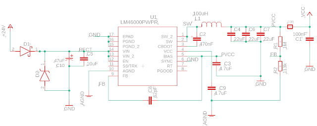
In the video we look at how to design a 24VAC power supply for industrial and HVAC applications. The supply will be flexible enough to handle DC voltage inputs. The power supply will employ a DC to DC buck converter, half wave rectifier, input protection against over voltage, and output noise reduction circuit features. In part 2 we look at the PCB design, the finished product, and capture some test data to see how it is working.
In the video we look at how to design a 24VAC power supply for industrial and HVAC applications. The supply will be flexible enough to handle DC voltage inputs. The power supply will employ a DC to DC buck converter, half wave rectifier, input protection against over voltage, and output noise reduction circuit features
Link to the ferrite bead article mentioned in the video: https://www.analog.com/en/analog-dialogue/articles/ferrite-beads-demystified.html#
Link to TI Webbench Power Designer tool: https://webench.ti.com/power-designer/switching-regulator
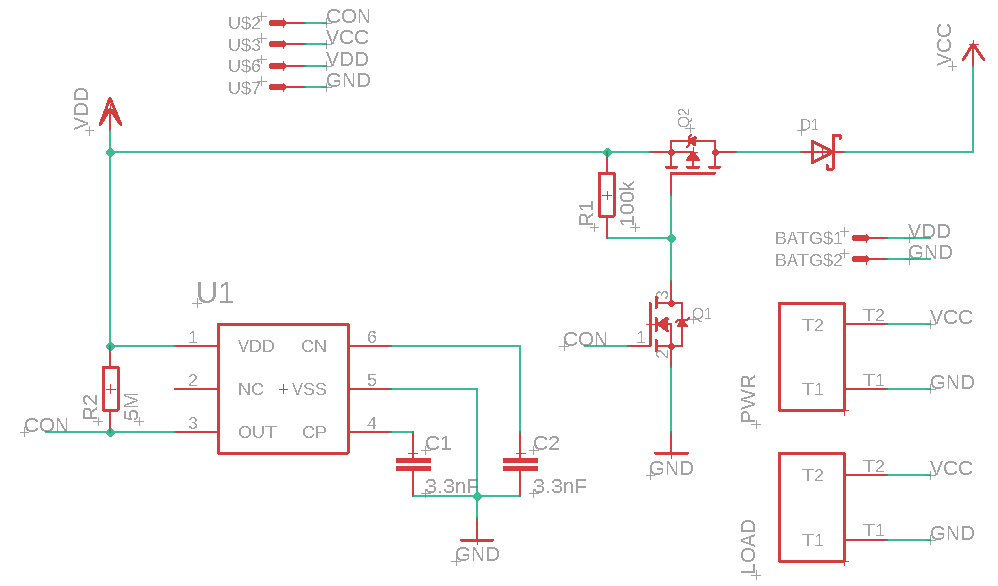
In this video we will design an automatic battery cutoff circuit to prevent damaging over discharge of rechargeable batteries. In part 2 we test the design and discuss MOSFET and Voltage Detector specs.
BOM of battery cutoff circuit:
S-1011A70-M6T1U4 Voltage Detector from ABLIC
DMP4015SSS-13 P Chan MOSFET from Diodes Inc
BSS138 N Chan MOSFET from multiple manufacturers
RSX051VYM30FHTR Schottky Diode from ROHM Semi
2x 3.3 nF Ceramic Capacitor
~100 kOhm Resistor
1 to 10 MOhm Resistor (used 4.7M in example circuit)
In this video we will design an automatic battery cutoff circuit to prevent damaging over discharge of rechargeable batteries. To design our battery cutoff circuit we will use a Voltage Detector or Reset IC.
In part two of this 4 or 5 part series, we look at how the Successive Approximation or SAR ADC architecture works and understand its limitations. Note SAR based ADC architecture is what you typically find in microcontrollers.
In this video series we look at ways or tips to improve ADC measurement accuracy and resolution. In part 1 define what accuracy and resolution is and different types of error that can affect ADC measurements. We also look at the importance of using an accurate ADC reference voltage and why you want to scale the range of the signal you are measuring to the ADC's range.
//***************Arduino code used in video******************************* /*This code demonstrates how to change the ADC voltage reference on an Arduino * This was shown in an ADC tutorial on the ForceTronics YouTube Channel. * This code is free and open for anybody to use at their own risk. */ void setup() { Serial.begin(115200); //setup serial connection while(!Serial); analogReference(AR_EXTERNAL); //sets the ADC reference voltage to external (input is aRef pin) //analogReference(AR_DEFAULT); //set the ADC reference to default which is AVCC (uses power supply voltage or VCC as reference) //analogReference(AR_INTERNAL2V23); //uses 2.23V internal reference in SAMD21 uC analogReadResolution(12); //Set ADC to 12bit resolution, default is 10 burn8Readings(); //make 8 readings but don't use them to ensure good reading after reference change delay(100); for(int i=0;i<500;i++) { //loop through a bunch of ADC readings and print them to serial plotter Serial.println(analogRead(A0)); //Make ADC measurement at A0 } } void loop() { //don't need the loop } //This function makes 8 ADC measurements but does nothing with them //Since after a reference change the ADC can return bad readings at first. This function is used to get rid of the first //8 readings to ensure an accurate one is displayed void burn8Readings() { for(int i=0; i<8; i++) { analogRead(A0); delay(1); } }
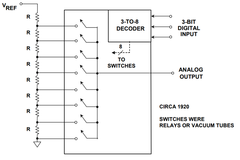
Two part tutorial on digital to analog converters (DAC). In part 2 we take a look at the capabilities of the MCP4728 which is a four channel DAC controlled via I2C. See the links below to access the code and get the PCB design from the video at PCBWay.
Link for PCB board at PCBWay: https://www.pcbway.com/project/shareproject/W08904ASW106_DAC_Example_Gerber.html
//**********Arduino Code with MCP4728 examples from video*************** /* * This code was written to demonstrate functions on the MCP4728 4 channel DAC for a video on the ForceTronics YouTube channel * This sketch leverages a library from GitHub made by Hideakitai, link to library: https://github.com/hideakitai/MCP4728 * This code is public domain and free to anyone to use and modify with no restrictions at your own risk */ #include <Wire.h> #include "MCP4728.h" MCP4728 dac; //create object to library //variables for wavform int const sampleCount = 24; //samples to read to have a buffer int signalSamples[sampleCount]; //create array to hold signal or waveform float pi2 = 6.283; //value of pi times 2 const long clkFrequency = 400000; //I2C clock frequency const uint8_t t1 = 3; //pin to setup test 1 fast sinewave const uint8_t t2 = 4; //pin to setup test 2 sync'd sinewaves const uint8_t LDAC = 5; //Output pin on MCU to control LDAC(not) pin on DAC void setup() { //Create sinewave float in; float hBit = 2047.5; for (int i=0;i<sampleCount;i++) { in = pi2*(1/(float)sampleCount)*(float)i; signalSamples[i] = (int)(sin(in)*hBit + hBit); } pinMode(t1,INPUT_PULLUP); //configure test check pins pinMode(t2,INPUT_PULLUP); //configure test check pins pinMode(LDAC,OUTPUT); //configure test check pins digitalWrite(LDAC,HIGH); //turn DAC outputs off Wire.begin(); //start up I2C library Wire.setClock(clkFrequency); //set clock frequency for I2C comm dac.attatch(Wire, 13); //second argument is Arduino pin connected to LDAC(not), we are controlling LDAC manually so just entered pin we are not using dac.readRegisters(); //Used to read current settings from MCP4728 dac.selectVref(MCP4728::VREF::VDD, MCP4728::VREF::VDD, MCP4728::VREF::VDD, MCP4728::VREF::VDD); //setup voltage ref for each DAC channel dac.selectPowerDown(MCP4728::PWR_DOWN::NORMAL, MCP4728::PWR_DOWN::NORMAL, MCP4728::PWR_DOWN::NORMAL, MCP4728::PWR_DOWN::NORMAL); //set power down mode, used for saving power dac.selectGain(MCP4728::GAIN::X1, MCP4728::GAIN::X1, MCP4728::GAIN::X1, MCP4728::GAIN::X1); //set gain on output amp //dac.enable(true); //enables the DAC outputs by controlling LDAC pin, but we are controlling LDAC manually in this example //perform test one if(!digitalRead(t1)) { digitalWrite(LDAC,LOW); //output sinewave as fast as we can for(;;) { //run test for infinitity for(int j=0;j<sampleCount;j++) { dac.analogWrite(MCP4728::DAC_CH::A,signalSamples[j]); } } } else { //perform test 2 for(;;) { //run test for infinitity for(int j=0;j<sampleCount;j++) { int temp = j; digitalWrite(LDAC,HIGH); //turn outputs off // delay(1); dac.analogWrite(MCP4728::DAC_CH::A,signalSamples[temp]); temp += 8; //shift sigal 90 degrees if(temp > 23) temp -= sampleCount; dac.analogWrite(MCP4728::DAC_CH::B,signalSamples[temp]); temp += 8; //shift sigal 90 degrees if(temp > 23) temp -= sampleCount; dac.analogWrite(MCP4728::DAC_CH::C,signalSamples[temp]); temp += 8; //shift sigal 90 degrees if(temp > 23) temp -= sampleCount; dac.analogWrite(MCP4728::DAC_CH::D,signalSamples[temp]); digitalWrite(LDAC,LOW); //turn outputs on all four outputs at same time // delay(1); } } } } void loop() { }
In this video we go over what a digital to analog converter (DAC) is and how it works. We then focus on the MCP4728 4 Channel DAC with some simple examples. In part two we do a deeper dive into the MCP4728.
In this video we unbox Particle's new IoT Mesh Network series (Argon, Boron, Xenon). We take a look both the hardware and the software that allows you to easily create a cloud connected mesh network. Link to product page: https://www.particle.io/mesh
//******************Code from Video***************************************** // ----------------------------------- // Controlling LEDs over the Internet // ----------------------------------- // First, let's create our "shorthand" for the pins // Same as in the Blink an LED example: // led1 is D0, led2 is D7 int led1 = D0; int led2 = D7; // Last time, we only needed to declare pins in the setup function. // This time, we are also going to register our Particle function void setup() { // Here's the pin configuration, same as last time pinMode(led1, OUTPUT); pinMode(led2, OUTPUT); // We are also going to declare a Particle.function so that we can turn the LED on and off from the cloud. Particle.function("led",ledToggle); // This is saying that when we ask the cloud for the function "led", it will employ the function ledToggle() from this app. // For good measure, let's also make sure both LEDs are off when we start: digitalWrite(led1, LOW); digitalWrite(led2, LOW); } // Last time, we wanted to continously blink the LED on and off // Since we're waiting for input through the cloud this time, // we don't actually need to put anything in the loop void loop() { // Nothing to do here } // We're going to have a super cool function now that gets called when a matching API request is sent // This is the ledToggle function we registered to the "led" Particle.function earlier. int ledToggle(String command) { /* Particle.functions always take a string as an argument and return an integer. Since we can pass a string, it means that we can give the program commands on how the function should be used. In this case, telling the function "on" will turn the LED on and telling it "off" will turn the LED off. Then, the function returns a value to us to let us know what happened. In this case, it will return 1 for the LEDs turning on, 0 for the LEDs turning off, and -1 if we received a totally bogus command that didn't do anything to the LEDs. */ if (command=="on") { digitalWrite(led1,HIGH); digitalWrite(led2,HIGH); Particle.publish("LED State", "ON"); return 1; } else if (command=="off") { digitalWrite(led1,LOW); digitalWrite(led2,LOW); Particle.publish("LED State", "OFF"); return 0; } else { return -1; } }
In this series we look at how to design a Thermocouple temperature measurement circuit. In part 2 we look at a real world example of a Thermocouple J Type circuit design and discuss some of the common sources of error and how to avoid them.
In this series we look at how to design a Thermocouple temperature measurement circuit. In part 1 we look at Thermocouple theory, pros and cons versus other temperature measurement techniques, and an overview of a measurement hardware circuit as well as calculations done in software.