Here is a link to the app note referenced in the video: http://www.ti.com/lit/an/spra953c/spra953c.pdf
Saturday, March 24, 2018
How to Calculate the Thermal Range of a Linear Regulator
In this video we look at how to determine whether an IC is going to work in a design from a thermal standpoint or is it going to get too hot and break / burn up. In the video we look at the popular LM317 Linear Regulator as an example.
Here is a link to the app note referenced in the video: http://www.ti.com/lit/an/spra953c/spra953c.pdf
Here is a link to the app note referenced in the video: http://www.ti.com/lit/an/spra953c/spra953c.pdf

Sunday, February 11, 2018
Converting an Arduino PWM Output to a DAC Output
In this video we look at how to convert a PWM output or signal to a analog or DAC signal.
To access the low pass filter tutorial mentioned in the video got to: https://youtu.be/gW5oF8vcYb8
//*************Arduino code from video***************************
/*This code was made for a vidoe tutorial on the ForceTronics YouTube Channel called
* Converting an Arduino PWM Output to a DAC Output. This code is free to use and
* modify at your own risk
*/
uint8_t pVal = 127; //PWM value
const float pi2 = 6.28; //Pie times 2, for building sinewave
const int samples = 100; //number of samples for Sinewave. This value also affects frequency
int WavSamples[samples]; //Array for storing sine wave points
int count = 0; //tracks where we are in sine wave array
void setup() {
// Serial.begin(115200); //for debugging
pinMode(10, OUTPUT); //pin used for analog voltage value
pinMode(4,OUTPUT); //pin used to fake PWM for sinewave
setPwmFrequency(10,1); //function for setting PWM frequency
analogWrite(10,127); //set duty cycle for PWM
float in, out; //used for building sine wave
for (int i=0;i<samples;i++) //loop to build sinewave
{
in = pi2*(1/(float)samples)*(float)i; //calculate value for sine function
WavSamples[i] = (int)(sin(in)*127.5 + 127.5); //get sinewave value and store in array
// Serial.println(WavSamples[i]); //for debugging
}
}
void loop() {
if(count > samples) count = 0; //reset the count once we are through array
bitBangPWM(WavSamples[count],4); //function for turning sinewave into "fake" PWM signal
count++; //increment position in array
}
//Function to bit bang a PWM signal (we are using it for the sinewave)
//input are PWM high value for one cycle and digital pin for Arduino
//period variable determines frequency along with number of signal samples
//For this example a period of 1000 (which is 1 millisecond) times 100 samples is 100 milli second period so 10Hz
void bitBangPWM(unsigned long on, int pin) {
int period = 1000; //period in micro seconds
on = map(on, 0, 255, 0, period); //map function that converts from 8 bits to range of period in micro sec
// Serial.println(on); //debug check
unsigned long start = micros(); //get current value of micro second timer as start time
digitalWrite(pin,HIGH); //set digital pin to high
while((start+on) > micros()); //wait for a time based on PWM duty cycle
start = micros();
digitalWrite(pin,LOW); //set digital pin to low
while((start+(period - on)) > micros()); //wait for a time based on PWM duty cycle
}
/**
* https://www.arduino.cc/en/Tutorial/SecretsOfArduinoPWM
* Divides a given PWM pin frequency by a divisor.
*
* The resulting frequency is equal to the base frequency divided by
* the given divisor:
* - Base frequencies:
* o The base frequency for pins 3, 9, 10, and 11 is 31250 Hz.
* o The base frequency for pins 5 and 6 is 62500 Hz.
* - Divisors:
* o The divisors available on pins 5, 6, 9 and 10 are: 1, 8, 64,
* 256, and 1024.
* o The divisors available on pins 3 and 11 are: 1, 8, 32, 64,
* 128, 256, and 1024.
*
* PWM frequencies are tied together in pairs of pins. If one in a
* pair is changed, the other is also changed to match:
* - Pins 5 and 6 are paired on timer0
* - Pins 9 and 10 are paired on timer1
* - Pins 3 and 11 are paired on timer2
*
* Note that this function will have side effects on anything else
* that uses timers:
* - Changes on pins 3, 5, 6, or 11 may cause the delay() and
* millis() functions to stop working. Other timing-related
* functions may also be affected.
* - Changes on pins 9 or 10 will cause the Servo library to function
* incorrectly.
*
* Thanks to macegr of the Arduino forums for his documentation of the
* PWM frequency divisors. His post can be viewed at:
* http://forum.arduino.cc/index.php?topic=16612#msg121031
*/
void setPwmFrequency(int pin, int divisor) {
byte mode;
if(pin == 5 || pin == 6 || pin == 9 || pin == 10) {
switch(divisor) {
case 1: mode = 0x01; break;
case 8: mode = 0x02; break;
case 64: mode = 0x03; break;
case 256: mode = 0x04; break;
case 1024: mode = 0x05; break;
default: return;
}
if(pin == 5 || pin == 6) {
TCCR0B = TCCR0B & 0b11111000 | mode;
} else {
TCCR1B = TCCR1B & 0b11111000 | mode;
}
} else if(pin == 3 || pin == 11) {
switch(divisor) {
case 1: mode = 0x01; break;
case 8: mode = 0x02; break;
case 32: mode = 0x03; break;
case 64: mode = 0x04; break;
case 128: mode = 0x05; break;
case 256: mode = 0x06; break;
case 1024: mode = 0x07; break;
default: return;
}
TCCR2B = TCCR2B & 0b11111000 | mode;
}
}
To access the low pass filter tutorial mentioned in the video got to: https://youtu.be/gW5oF8vcYb8
//*************Arduino code from video***************************
/*This code was made for a vidoe tutorial on the ForceTronics YouTube Channel called
* Converting an Arduino PWM Output to a DAC Output. This code is free to use and
* modify at your own risk
*/
uint8_t pVal = 127; //PWM value
const float pi2 = 6.28; //Pie times 2, for building sinewave
const int samples = 100; //number of samples for Sinewave. This value also affects frequency
int WavSamples[samples]; //Array for storing sine wave points
int count = 0; //tracks where we are in sine wave array
void setup() {
// Serial.begin(115200); //for debugging
pinMode(10, OUTPUT); //pin used for analog voltage value
pinMode(4,OUTPUT); //pin used to fake PWM for sinewave
setPwmFrequency(10,1); //function for setting PWM frequency
analogWrite(10,127); //set duty cycle for PWM
float in, out; //used for building sine wave
for (int i=0;i<samples;i++) //loop to build sinewave
{
in = pi2*(1/(float)samples)*(float)i; //calculate value for sine function
WavSamples[i] = (int)(sin(in)*127.5 + 127.5); //get sinewave value and store in array
// Serial.println(WavSamples[i]); //for debugging
}
}
void loop() {
if(count > samples) count = 0; //reset the count once we are through array
bitBangPWM(WavSamples[count],4); //function for turning sinewave into "fake" PWM signal
count++; //increment position in array
}
//Function to bit bang a PWM signal (we are using it for the sinewave)
//input are PWM high value for one cycle and digital pin for Arduino
//period variable determines frequency along with number of signal samples
//For this example a period of 1000 (which is 1 millisecond) times 100 samples is 100 milli second period so 10Hz
void bitBangPWM(unsigned long on, int pin) {
int period = 1000; //period in micro seconds
on = map(on, 0, 255, 0, period); //map function that converts from 8 bits to range of period in micro sec
// Serial.println(on); //debug check
unsigned long start = micros(); //get current value of micro second timer as start time
digitalWrite(pin,HIGH); //set digital pin to high
while((start+on) > micros()); //wait for a time based on PWM duty cycle
start = micros();
digitalWrite(pin,LOW); //set digital pin to low
while((start+(period - on)) > micros()); //wait for a time based on PWM duty cycle
}
/**
* https://www.arduino.cc/en/Tutorial/SecretsOfArduinoPWM
* Divides a given PWM pin frequency by a divisor.
*
* The resulting frequency is equal to the base frequency divided by
* the given divisor:
* - Base frequencies:
* o The base frequency for pins 3, 9, 10, and 11 is 31250 Hz.
* o The base frequency for pins 5 and 6 is 62500 Hz.
* - Divisors:
* o The divisors available on pins 5, 6, 9 and 10 are: 1, 8, 64,
* 256, and 1024.
* o The divisors available on pins 3 and 11 are: 1, 8, 32, 64,
* 128, 256, and 1024.
*
* PWM frequencies are tied together in pairs of pins. If one in a
* pair is changed, the other is also changed to match:
* - Pins 5 and 6 are paired on timer0
* - Pins 9 and 10 are paired on timer1
* - Pins 3 and 11 are paired on timer2
*
* Note that this function will have side effects on anything else
* that uses timers:
* - Changes on pins 3, 5, 6, or 11 may cause the delay() and
* millis() functions to stop working. Other timing-related
* functions may also be affected.
* - Changes on pins 9 or 10 will cause the Servo library to function
* incorrectly.
*
* Thanks to macegr of the Arduino forums for his documentation of the
* PWM frequency divisors. His post can be viewed at:
* http://forum.arduino.cc/index.php?topic=16612#msg121031
*/
void setPwmFrequency(int pin, int divisor) {
byte mode;
if(pin == 5 || pin == 6 || pin == 9 || pin == 10) {
switch(divisor) {
case 1: mode = 0x01; break;
case 8: mode = 0x02; break;
case 64: mode = 0x03; break;
case 256: mode = 0x04; break;
case 1024: mode = 0x05; break;
default: return;
}
if(pin == 5 || pin == 6) {
TCCR0B = TCCR0B & 0b11111000 | mode;
} else {
TCCR1B = TCCR1B & 0b11111000 | mode;
}
} else if(pin == 3 || pin == 11) {
switch(divisor) {
case 1: mode = 0x01; break;
case 8: mode = 0x02; break;
case 32: mode = 0x03; break;
case 64: mode = 0x04; break;
case 128: mode = 0x05; break;
case 256: mode = 0x06; break;
case 1024: mode = 0x07; break;
default: return;
}
TCCR2B = TCCR2B & 0b11111000 | mode;
}
}
Wednesday, January 31, 2018
Designing a Driver Circuit for a Bipolar Stepper Motor Part 2
In this video we design a low cost driver circuit for a four wire bipolar stepper motor using two H bridges.
Link to Eagle files on GitHub: https://github.com/ForceTronics/Bipolar_Stepper_Driver_Circuit/tree/master

Link to Eagle files on GitHub: https://github.com/ForceTronics/Bipolar_Stepper_Driver_Circuit/tree/master

Sunday, January 7, 2018
Getting Your First PCB Design Manufactured
In this video we go over how to take your PCB design from software and get it manufactured. We cover everything from PCB CAD software packages, to generating your Gerber files, and finish with understanding the different options PCB manufacturers offer.
Wednesday, December 27, 2017
Designing a Driver Circuit for a Bipolar Stepper Motor Part 1
In this video we design a low cost driver circuit for a four wire bipolar stepper motor using two H bridges.

//********************Arduino code from video***********************
#include <Stepper.h>
const int numberOfSteps = 100; //number of steps you want your stepper motor to take
// initialize the stepper library on pins 8 through 11:
Stepper myStepper(numberOfSteps, 8, 9, 10, 11);
void setup() {
// set the speed at 60 rpm:
myStepper.setSpeed(60);
}
void loop() {
myStepper.step(numberOfSteps);
delay(1000);
}

//********************Arduino code from video***********************
#include <Stepper.h>
const int numberOfSteps = 100; //number of steps you want your stepper motor to take
// initialize the stepper library on pins 8 through 11:
Stepper myStepper(numberOfSteps, 8, 9, 10, 11);
void setup() {
// set the speed at 60 rpm:
myStepper.setSpeed(60);
}
void loop() {
myStepper.step(numberOfSteps);
delay(1000);
}
Tuesday, December 12, 2017
Ultimate Battery Circuit Design Part 2
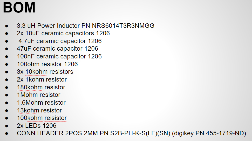
In this video series we build the ultimate battery circuit that can handle various battery chemistry's, charge batteries, perform load sharing during charging, handle input voltage levels that are higher or lower than the output, and more. In part 2 we will look at the PCB layout with a focus on the buck boost DC to DC Converter and look at the BOM.



Sunday, December 3, 2017
Ultimate Battery Circuit Design Part 1
In this video series we build the ultimate battery circuit that can handle various battery chemistry's, charge batteries, perform load sharing during charging, handle input voltage levels that are higher or lower than the output, and more. In part 1 we will look at the circuit configuration and component values that we plan to use.


Subscribe to:
Posts (Atom)